Light reflecting devices incorporating composite reflecting structures

a technology of composite reflecting structures and light reflecting devices, which is applied in the direction of instruments, lighting and heating apparatuses, optical elements, etc., can solve the problems of affecting the light-redirecting performance of mirror structures incorporating aluminum components, the difficulty of aluminum components being integrated into heliostat designs, and the relatively high coefficient of thermal expansion of aluminum, etc., to achieve the effect of stiff substrate structur

a technology of composite reflecting structures and light reflecting devices, which is applied in the direction of instruments, lighting and heating apparatuses, optical elements, etc., can solve the problems of affecting the light-redirecting performance of mirror structures incorporating aluminum components, the difficulty of aluminum components being integrated into heliostat designs, and the relatively high coefficient of thermal expansion of aluminum, etc., to achieve the effect of stiff substrate structur

US20180129015A1Inactive Publication Date: 2018-05-10SOLARRESERVE TECH

Image

  • Light reflecting devices incorporating composite reflecting structures
  • Light reflecting devices incorporating composite reflecting structures
  • Light reflecting devices incorporating composite reflecting structures

Examples


Embodiment Construction

[0086]The present invention will now be further described with reference to the following illustrative embodiments. The embodiments described below are not intended to be exhaustive or to limit the invention to the precise forms disclosed in the following detailed description. Rather a purpose of the embodiments chosen and described is so that the appreciation and understanding by others skilled in the art of the principles and practices of the present invention can be facilitated.

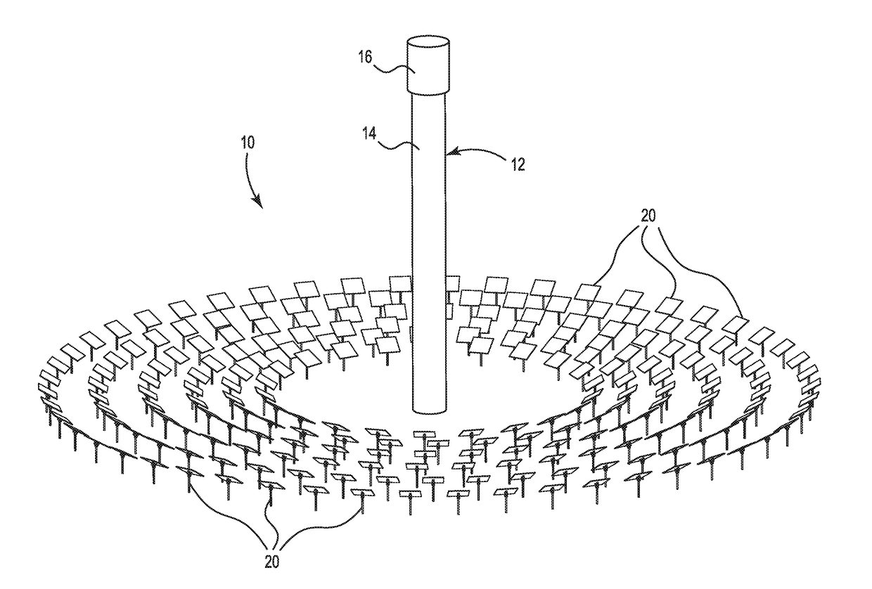
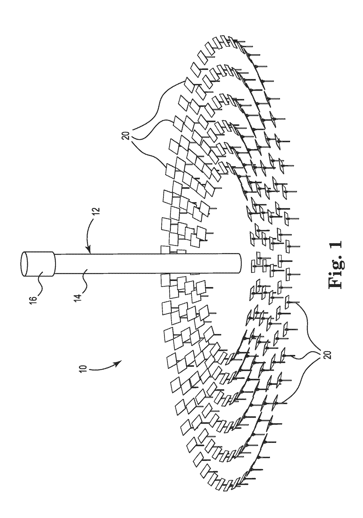
[0087]Referring to the figures, FIG. 1 schematically illustrates a concentrating solar energy system 10 that incorporates principles of the present invention. System 10 includes a central tower 12 including a mast 14 and a target region 16 at the top of the mast. A field of heliostats 20 is deployed around central tower 12. The heliostats 20 redirect and concentrate incident sunlight onto target region 16. If system 10 embodies a photovoltaic solar power system (a.k.a. concentrating photovoltaics, or CPV),...


PUM


Abstract

In illustrative modes of practice, heliostat devices integrate light reflecting panels with a composite supporting structure that helps to provide the resultant assembly with structural integrity and stiffness. Light reflecting panels are coupled to the supporting, composite structure by a plurality of flexible connecting elements. Advantageously, the composite approach of the present invention effectively separates structural and thermal compensation functions. Specifically, the composite support structure helps to provide desired structural properties. In the meantime, the flexible connecting elements couple the top, light reflecting panel to the support structure in a manner that helps to isolate the top, light reflecting panel from thermal stresses that otherwise could cause undue slope errors.

Description

PRIORITY[0001]This application claims the benefit of U.S. Provisional Patent Application Ser. No. 62 / 153,723, filed on Apr. 28, 2015; U.S. Provisional Patent Application Ser. No. 62 / 153,716 filed on Apr. 28, 2015; and U.S. Provisional Patent Application Ser. No. 62 / 211,376, filed on Aug. 28, 2015, which are incorporated herein by reference in their entirety for all purposes.FIELD OF THE INVENTION[0002]The present invention relates to light reflecting devices used for redirecting light to a target. More specifically, the light redirecting devices incorporate composite reflecting structures in which light reflecting surfaces are more stable and less prone to slope errors that might otherwise result from temperature changes.BACKGROUND[0003]Many useful devices incorporate features that reflect incident light. Examples of such devices include mirrors, heliostats, siderostats, coelostats, trough reflectors, dish reflectors, solar trackers, and other similar devices that are useful in syst...

Claims


Application Information

Patent Timeline
10 May 2018
Publication
US20180129015A1
IPC
G02B7/18; G02B7/183; G02B19/00; H02S40/22; F24S20/20; F24S20/30; F24S23/70; F24S50/20
CPC
F24S20/30; F24S2020/15; G02B7/181; G02B7/183; G02B19/0019; F24J2002/0076; H02S40/22; F24J2/02
Inventors
GREGORY, CHRISTIAN; GREEN, ADAM