Electronic device with electromagnetic shielding member

a shielding member and electromagnetic technology, applied in the field of electronic devices, can solve the problems of deteriorating the operating performance of the ic chip and/or affecting and affecting the overall performance of the electronic device, so as to achieve the effect of convenient disposal and improving the degree of design freedom

Active Publication Date: 2018-05-10
SAMSUNG ELECTRONICS CO LTD
View PDF3 Cites 29 Cited by
  • Summary
  • Abstract
  • Description
  • Claims
  • Application Information

AI Technical Summary

Benefits of technology

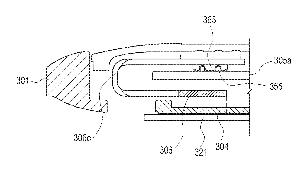
[0010]An aspect of the present disclosure provides an electronic device including a shielding member in which a circuit board and / or an IC chip may also be easily disposed even in a narrow space, thereby improving the degree of design freedom.

Problems solved by technology

However, various IC chips with increased integration may generate additional electromagnetic waves, and the interference of these electromagnetic waves may degrade a performance of the IC chips and / or an overall performance of an electronic device.
However, such an arrangement may deteriorate an operating performance of the IC chips and / or an operating environment of the antenna devices.

Method used


Image

  • Electronic device with electromagnetic shielding member
  • Electronic device with electromagnetic shielding member
  • Electronic device with electromagnetic shielding member

Examples


Embodiment Construction

[0024]Embodiments of the present disclosure will be described herein below with reference to the accompanying drawings. However, the embodiments of the present disclosure are not limited to the specific embodiments and should be construed as including all modifications, changes, equivalent devices and methods, and / or alternative embodiments of the present disclosure. In the description of the drawings, similar reference numerals are used for similar elements.

[0025]The terms “have,”“may have,”“include,” and “may include” as used herein indicate the presence of corresponding features (for example, elements such as numerical values, functions, operations, or parts), and do not preclude the presence of additional features.

[0026]Further, the terms “a front surface”, “a rear surface”, “a top surface”, “a bottom surface”, etc., which are described with respect to the orientation in the drawings, may be replaced by ordinal numbers such as first and second. The terms “A or B,”“at least one o...


PUM

PropertyMeasurementUnit
widthaaaaaaaaaa
lengths L1aaaaaaaaaa

Abstract

An electronic device is provided. The electronic device includes a housing including a radiating conductor forming a portion of a side wall thereof, an electronic component disposed adjacent to the radiating conductor, a circuit board including an integrated circuit (IC) chip, and a shielding member attached to the circuit board and surrounding the IC chip.

Description

PRIORITY[0001]This application claims priority under 35 U.S.C. § 119(a) to Korean Patent Application Serial No. 10-2016-0148150, which was filed in the Korean Intellectual Property Office on Nov. 8, 2016, the entire content of which is incorporated herein by reference.BACKGROUND1. Field of the Disclosure[0002]The present disclosure relates generally to an electronic device, and more particularly, to an electronic device including a shielding member that prevents electromagnetic wave interference.2. Description of the Related Art[0003]Conventional electronic devices (e.g., an electronic scheduler, a portable multimedia reproducer, a mobile communication terminal, a tablet PC, an image / sound device, a desktop / laptop PC, a home appliance or a vehicular navigation system) are configured to perform one or more functions according to the various programs or applications installed thereon. For example, an electronic device may output information stored thereon as sound or an image. As the ...

Claims


Application Information

Patent Timeline
Patent Type & Authority Applications(United States)
IPC IPC(8): H01Q1/52H01L23/552H05K1/18H05K9/00H05K1/11H05K1/14G06F3/041H01Q1/48H01Q1/24H01Q1/22
CPCH01Q1/526H01L23/552H05K1/181H05K9/0024H05K1/111H05K1/147G06F3/0412H01Q1/48H01Q1/243H01Q1/2283H05K2201/056H05K2201/042H05K2201/10128H05K2201/10151G06F3/044G06F3/0414H04M1/0266H04M1/03H04M1/0277H01Q9/42H05K1/0218H05K2201/0715H01L2224/16227H01L2924/19105H01L2924/3025H05K9/003H05K9/0026H05K9/0083H05K9/0064B32B15/20G06F3/041C09J163/00B32B2307/212
Inventor KIM, JUN-YOUNGKIM, SANG-SEOBPARK, MINBANG, JUNG-JEKIM, BEOM-JUYE, JAE-HEUNGLEE, YONG-WONPARK, JUNG-SIK
Owner SAMSUNG ELECTRONICS CO LTD
Why Eureka
Try Eureka