Eye nebulizer

a nebulizer and eye technology, applied in the field of nebulizers, can solve the problems of eye discomfort or even harm, eye injury, etc., and achieve the effects of enhancing treatment effect, preventing the nebulized medication from directly affecting and injuring the eye, and widening the treatment area around the ey

Inactive Publication Date: 2018-05-17
HUANG YU KANG
View PDF2 Cites 4 Cited by
  • Summary
  • Abstract
  • Description
  • Claims
  • Application Information

AI Technical Summary

Benefits of technology

[0004]Therefore, an objective of the present invention is to provide a novel eye nebulizer that, by deploying at least a block piece along a tube for the nebulized medication, alters a flow path of the nebulized medication into an S-shaped one, thereby preventing the nebulized medication from directly impacting and injuring the eye. In addition, due to the altered and curved flow path, the nebulized medication would diffuse around the rim of the eye cup, thereby covering a wider treatment area around the eye. The eye nebulizer therefore achieves an enhanced treatment effect and a greater applicability.
[0005]The eye nebulizer includes a nebulization unit, an eye cup, and a tube respectively connecting the eye cup and the nebulization unit. The tube includes a channel connecting the nebulization unit and the eye cup, a wall surrounding the channel, and at least a block piece inside the channel configured on the wall and forming an S-shaped flow path for the nebulized medication flowing through the channel. Due to the S-shaped flow path, the nebulized medication would diffuse around the rim of the eye cup, thereby covering a wider treatment area around the eye. The eye nebulizer therefore achieves an enhanced treatment effect and a greater applicability.

Problems solved by technology

If the nebulization unit 11 produces too strong a pressure and the nebulized medication would be sprayed towards the eye in a jet stream, causing uncomfortableness or even harm to the eye.
Additionally, if a user directly apply the eye nebulizer 1 without checking and removing foreign object or debris attached to the nozzle 114 or the tube 13, the foreign object or debris may impact the eye along with the nebulized medication, thereby injuring the eye.

Method used


Image

  • Eye nebulizer
  • Eye nebulizer
  • Eye nebulizer

Examples


Embodiment Construction

[0014]The following descriptions are exemplary embodiments only, and are not intended to limit the scope, applicability or configuration of the invention in any way. Rather, the following description provides a convenient illustration for implementing exemplary embodiments of the invention. Various changes to the described embodiments may be made in the function and arrangement of the elements described without departing from the scope of the invention as set forth in the appended claims.

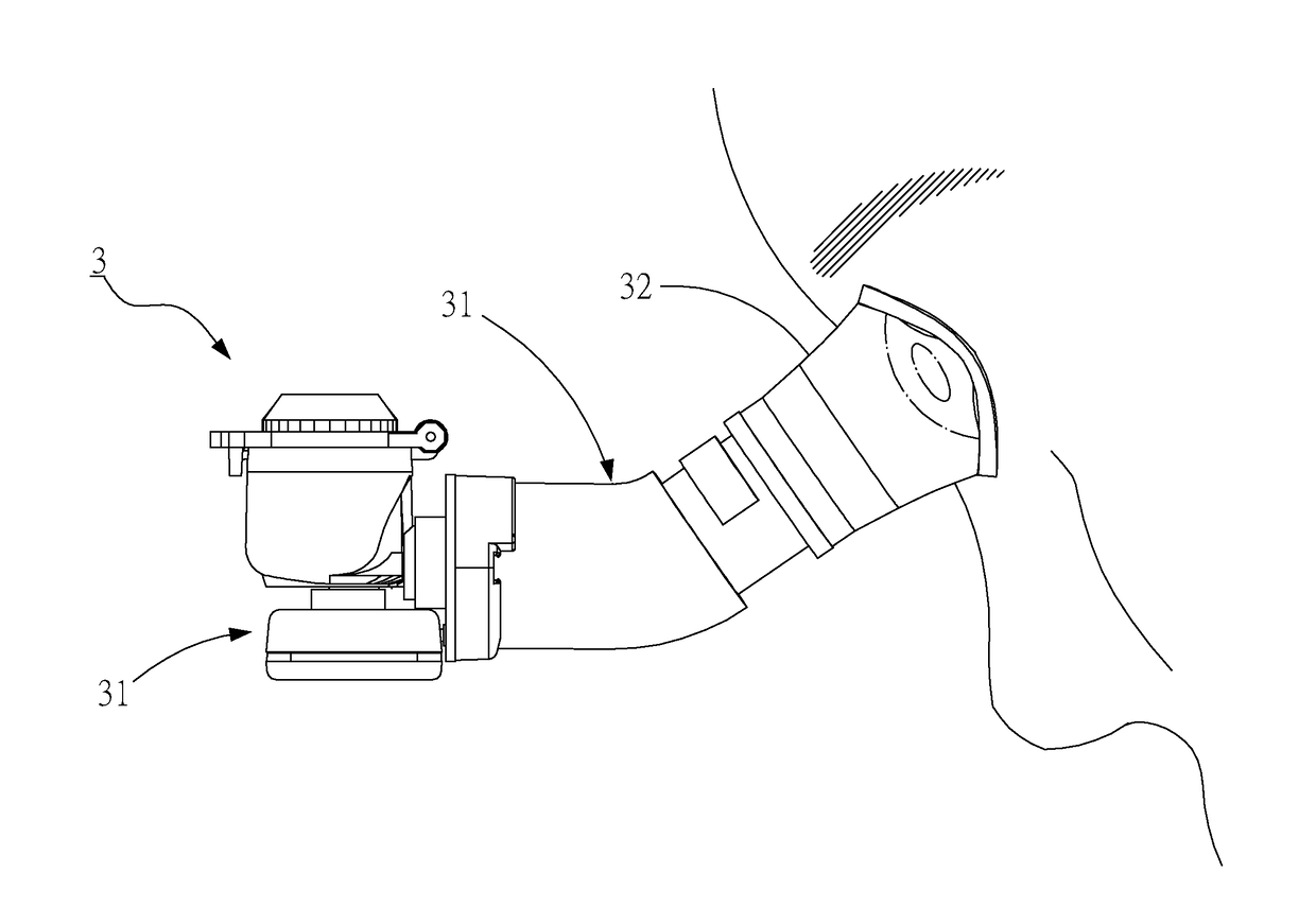
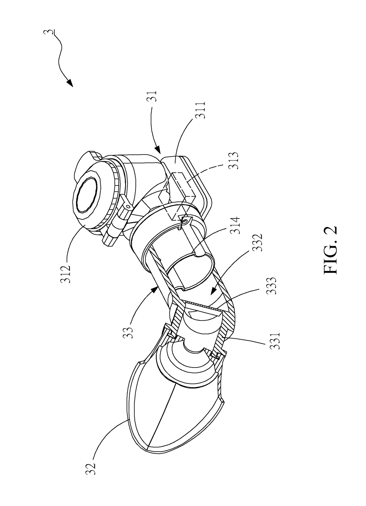
[0015]As shown in FIG. 2, an eye nebulizer 3 according to an embodiment of the present invention includes a nebulization unit 31, an eye cup 32, and a tube 33 respectively connecting the eye cup 32 and the nebulization unit 31. The nebulization unit 31 includes a main member 311, a reservoir member 312 configured on the main member 311 and storing a medication (not shown), a vibrator module 313 (indicated by the dotted box) inside the main member 311 for nebulizing the medication stored in the reser...


PUM


Abstract

The eye nebulizer deploys at least a block piece along a tube for the nebulized medication so as to achieve an S-shaped flow path, thereby preventing the nebulized medication from directly impacting and injuring the eye. In addition, due to the altered and curved flow path, the nebulized medication would diffuse around the rim of the eye cup, thereby covering a wider treatment area around the eye. The eye nebulizer therefore achieves an enhanced treatment effect and a greater applicability.

Description

BACKGROUND OF THE INVENTIONa) Technical Field of the Invention[0001]The present invention is generally related to nebulizers, and more particular to a nebulizer for eye treatment.(b) Description of the Prior Art[0002]As shown in FIG. 1, a conventional eye nebulizer 1 includes a nebulization unit 11, an eye cup 12, and a tube 13 respectively connecting the eye cup 12 and the nebulization unit 11. The nebulization unit 11 includes a main member 111, a reservoir member 112 configured on the main member 111 and storing a medication (not shown), a vibrator module 113 (indicated by the dotted box) inside the main member 111 for nebulizing the medication stored in the reservoir member 112, and a nozzle 114 configured on the main member 111 and connecting the tube 13 to release the nebulized medication. The tube 13 has a channel 132 surrounded by a wall 131 and connecting the nozzle 114 so as to allow the nebulized medication to pass through. To operate the eye nebulizer 1, the eye cup 12 i...

Claims


Application Information

Patent Timeline
Patent Type & Authority Applications(United States)
IPC IPC(8): A61F9/00A61M11/00
CPCA61M11/00A61F9/0008A61M2202/0468A61F9/0026A61M2210/0612A61M11/005
Inventor HUANG, YU-KANG
Owner HUANG YU KANG
Why Eureka
Try Eureka