Nozzle for continuous casting

a technology of continuous casting and nozzle, which is applied in the direction of furnaces, manufacturing converters, liquid transfer devices, etc., can solve the problems of reduced tensile strength and/or resilience, excessive susceptibility to work hardening, and reduced friction, etc., and achieves good uniform temperature and low speed

Inactive Publication Date: 2006-11-28
DANIELI & C OFF MEC SPA
View PDF7 Cites 6 Cited by
  • Summary
  • Abstract
  • Description
  • Claims
  • Application Information

AI Technical Summary

Benefits of technology

[0012]With a number, configuration and arrangement of discharge channels of this sort, the upwardly directed flows of liquid metal have a low speed and are distributed uniformly over the entire section of the crystallizer, thus ensuring: (i) a good uniformity of temperature of the liquid metal at the level of the meniscus; (ii) a complete liquefaction of the lubricating powder; and (iii) the absence of vortices at the level of the meniscus, which might determine trapping of the lubricating powder.
[0013]On the other hand, also the downwards directed flows are uniform and relatively “gentle”, so enabling any possible gas bubbles and inclusions drawn along by the liquid metal to return back up towards the meniscus. In addition, the direct impact of the jet of liquid metal against the skin that is solidifying is prevented, so eliminating, or at least markedly reducing, the so-called “washing” phenomenon.

Problems solved by technology

The liquefied lubricating powder which floats on the molten metal works its way between the solidified skin and the walls of the crystallizer, so diminishing friction.
Continuous-casting technology has undergone numerous improvements over time, in particular linked to the casting rate and to internal and surface defects of the cast products.
In fact, such defects reflect on the surface finish of the end product, which in many cases has to be impeccable, as e.g. for carbon-steel coils for car bodies, or for stainless-steel coils for architectural or aesthetic uses (decorative panels, kitchen-sink surfaces, cooking surfaces, pots and pans, etc.)), or even on the mechanichanical characteristics of the finished product (for example, excessive susceptibility to work hardening; reduced tensile strength and / or resilience, etc.).
A further source of defects is represented by the fact that little circulation of molten metal is possible between the mouth of the nozzle and the layer of supernatant lubricating powder, with the result that the latter may not melt adequately, i.e., in such a way as to guarantee the necessary lubrication between the skin that is forming and the walls of the crystallizer.
However, the geometry of this nozzle only allows a limited diameter of the discharging holes.
Below the nozzle inhomogeneous temperatures are moreover formed, which adversely affect the quality of the cast.
Experience has shown, however, that, albeit representing an improvement over previous nozzles, a nozzle having the above structure is, on the one hand, suitable only for continuous casting of thin slabs, whereas on the other it does not achieve completely the advantages set forth in the description.
In particular, the problem remains, which is moreover common to all nozzles, of the poor feed of molten metal upwards in the region around the descending duct of the nozzle.
In this region, the vicinity of the cooled walls of the crystallizer to the nozzle, combined with a poor circulation of the molten metal coming directly from the nozzle, and hence at maximum temperature, easily causes the formation of cold spots.
In addition, the relatively low temperature around the nozzle may lead to the failure of the supernatant lubricating powder to melt in situ, with possible drawing along of solid particles of lubricating powder in the solidification zone.

Method used


Image

  • Nozzle for continuous casting
  • Nozzle for continuous casting
  • Nozzle for continuous casting

Examples


first embodiment

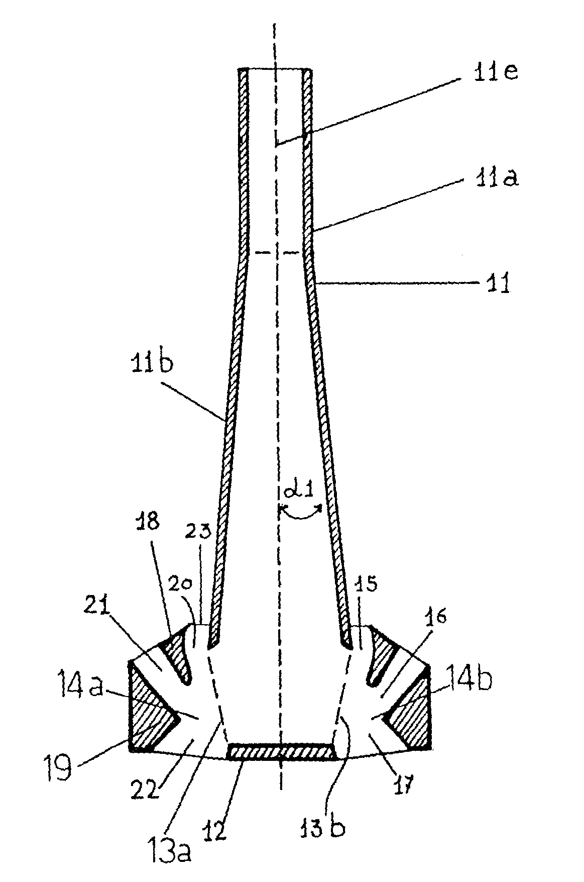
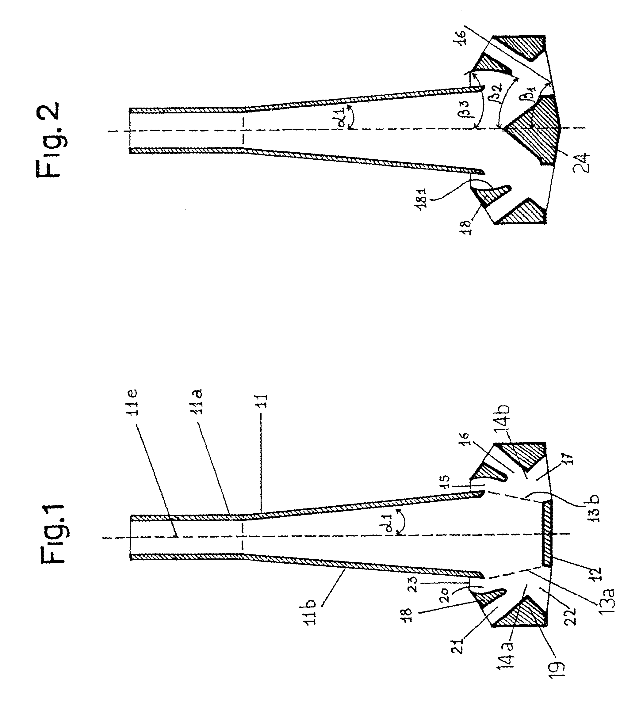
[0015]FIG. 1 is a longitudinal sectional view of a nozzle according to the invention;

second embodiment

[0016]FIG. 2 is a longitudinal sectional view of a nozzle according to the invention;

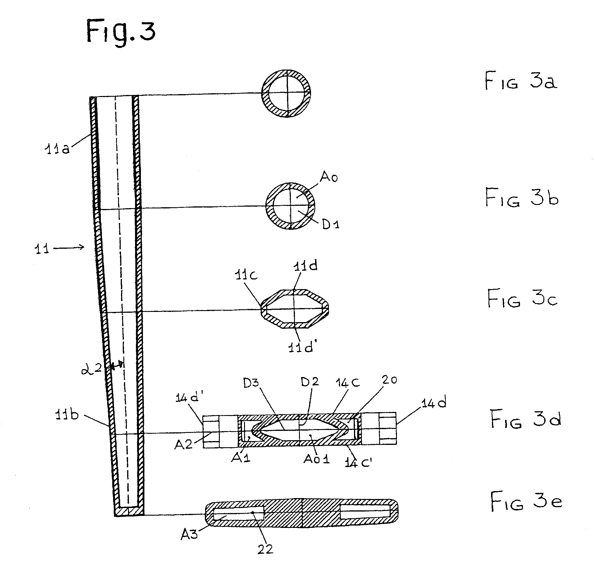
[0017]FIG. 3 is a longitudinal sectional view of the nozzle of FIG. 1, according to a plane orthogonal to the plane of FIG. 1;

[0018]FIGS. 3a–3e each show a cross section of the nozzle of FIG. 3.

[0019]In the figures, similar parts are identified by the same reference numbers; in addition, for reasons of simplicity, in one and the same figure with specular parts, some reference numbers are indicated in one of the parts and other reference numbers in the other. Finally, some of the reference numbers indicated in one figure may not be indicated in another figure, in order to prevent any reading mistakes. However, it is understood that the said reference numbers and indications are valid for all the similar figures.

[0020]The nozzle according to the present invention is used for continuous feeding a liquid metal into a crystallizer for the continuous casting of slabs, preferably having a medium to small t...


PUM

PropertyMeasurementUnit
angle β1aaaaaaaaaa
angle β1aaaaaaaaaa
trailing angles β3aaaaaaaaaa

Abstract

An arrangement and conformation of the discharge openings and channels of a continuous-casting nozzle, together with a specific external profile of the body of the nozzle itself, enable slabs of any thickness, in particular from medium to thin ones, to be cast, which have excellent surface quality and are practically free from inclusions and blowholes.

Description

FIELD OF THE INVENTION[0001]The present invention refers to an improved nozzle for continuous casting, and more precisely refers to a nozzle suitable for casting slabs, in particular slabs of small and medium thickness, with high casting rates and improved surface and internal quality of the cast slabs.STATE OF THE ART[0002]As is known, continuous casting of metals and metallic alloys, in particular steel, consists in transferring, via a refractory material duct referred to as “nozzle”, the molten metal from a first container, called “tundish”, having the function of distributor and equaliser of the flow, into a second bottomless container, called “ingot mould” or “crystallizer”, which is strongly cooled by means of water circulation. At the start of casting, the crystallizer is closed at the bottom by a mobile body referred to as “dummy bar”. The molten metal contained in the crystallizer is protected from oxidation at high temperature by means of a layer of lubricating powder, whi...

Claims


Application Information

Patent Timeline
Patent Type & Authority Patents(United States)
IPC IPC(8): C21C5/42B22D41/50
CPCB22D41/50
Inventor KAPAJ, NUREDINPAVLICEVIC, MILORADPOLONI, ALFREDOVECCHIET, FABIO
Owner DANIELI & C OFF MEC SPA
Why Eureka
Try Eureka