
Method of and Apparatus for Shot Peening Stainless Steel Tubing

a technology of stainless steel tubing and apparatus, which is applied in the direction of heat treatment apparatus, furnaces, furnaces, etc., can solve the problems of unplanned shutdown of power generation facilities, reduced cold working efficiency imparted to the tube surface, and loss of a portion of the kinetic energy of the sho

Inactive Publication Date: 2014-12-25
FOSTER WHEELER NORTH AMERICA CORP
View PDF6 Cites 7 Cited by
  • Summary
  • Abstract
  • Description
  • Claims
  • Application Information

AI Technical Summary

Benefits of technology

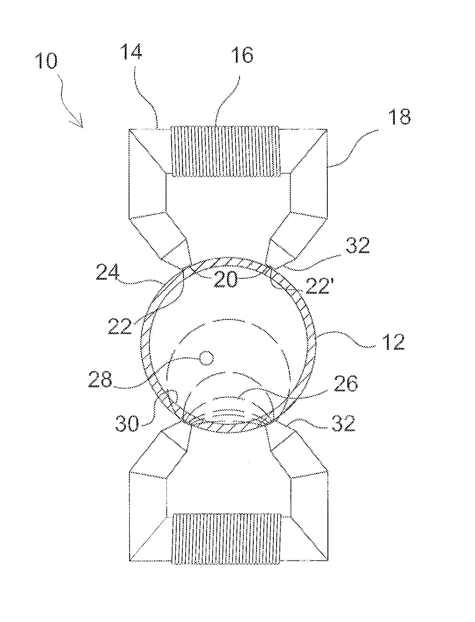
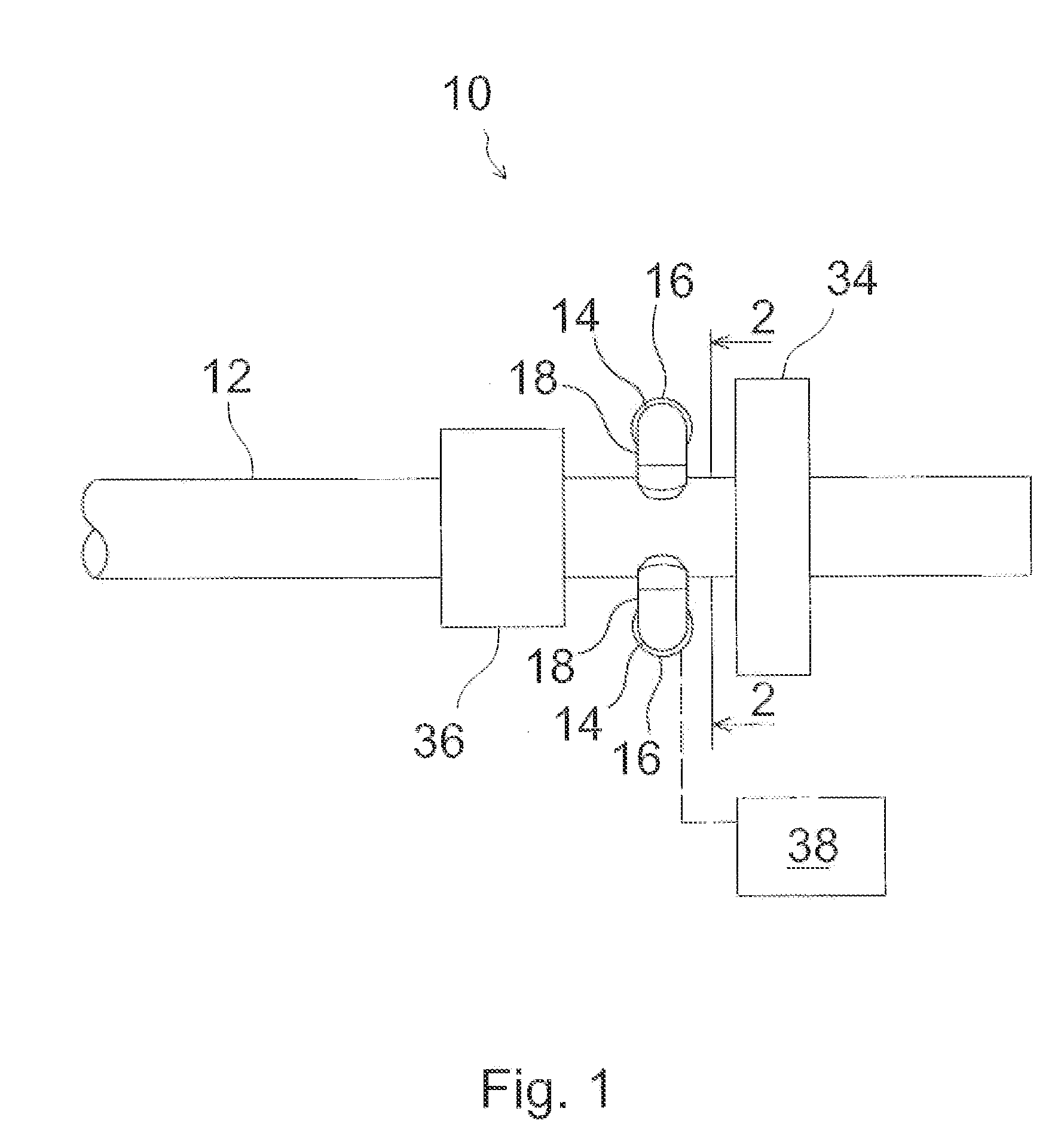
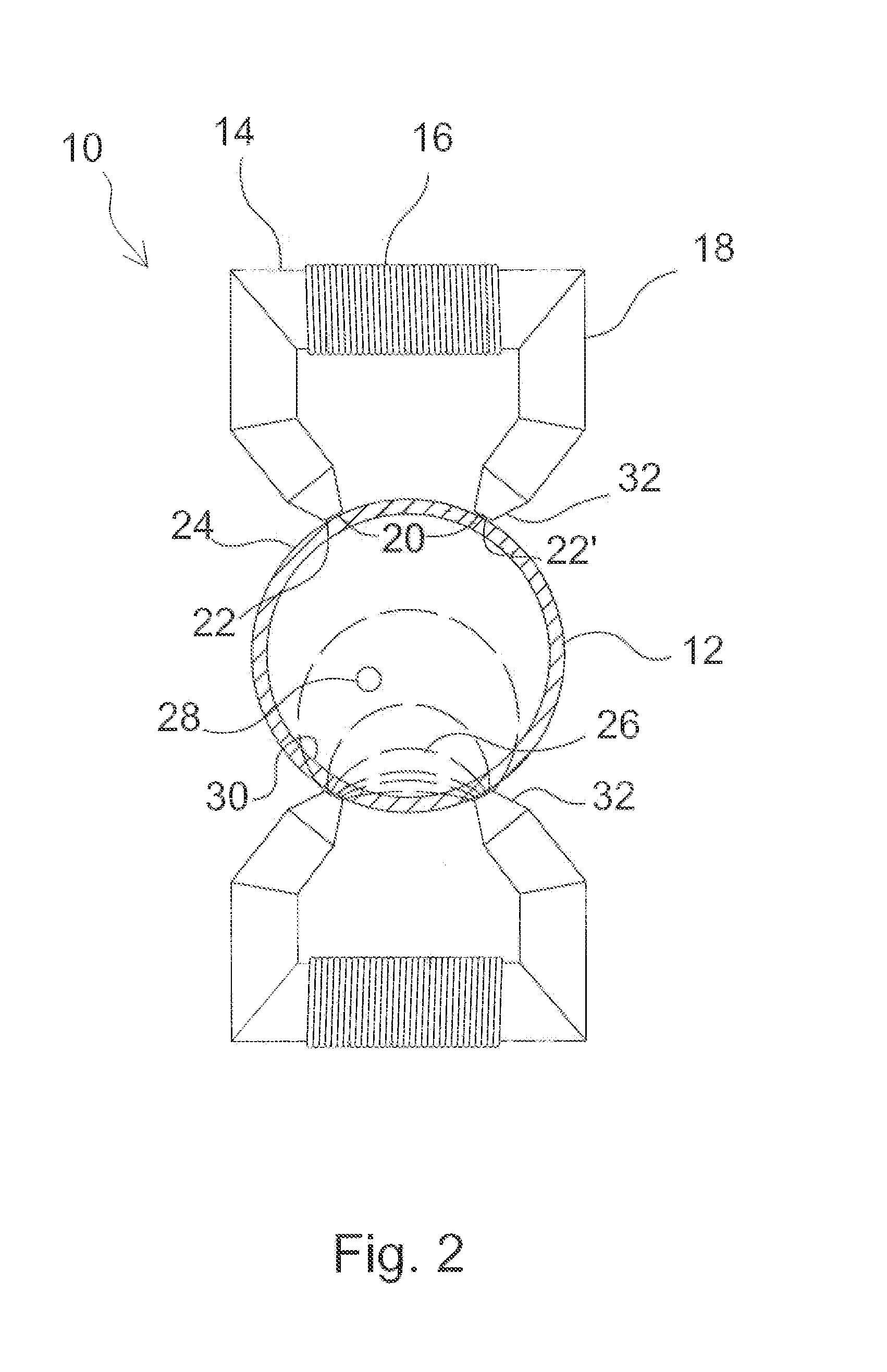
The invention is a method of cold working the interior of a stainless steel tube using electromagnets to accelerate steel balls and create impacts on the tube wall. This process results in a high amount of kinetic energy being delivered to the tube surface, making it highly efficient. The method has the advantage of achieving a high incident angle of impact, meaning the steel shot is delivered with greater force and impact. Additionally, there is no need for a diverter plate that requires regular maintenance.

Problems solved by technology

Steam-side oxidation and the resultant exfoliation of iron-based scales cause unplanned shutdowns at power generation facilities.
Another weakness of the method is that the efficiency of the cold working imparted to the tube surface is decreased due to a relatively low incident angle of shot impact.
A portion of the kinetic energy of the shot is also lost by friction along the lance, and by impact with the diverter plate.
During the peening operation, the diverter plate experiences high wearing, which again, affects the efficiency of the cold working.

Method used


Image

  • Method of and Apparatus for Shot Peening Stainless Steel Tubing
  • Method of and Apparatus for Shot Peening Stainless Steel Tubing
  • Method of and Apparatus for Shot Peening Stainless Steel Tubing

Examples


third embodiment

[0038]FIG. 5 schematically shows a cross-sectional view corresponding to FIGS. 2 and 4 of the present invention for shot peening a cross section of a stainless steel tube 12. (FIG. 5 also shows a cross section across the tube taken along line 4-4 of FIG. 3.) The shot peening apparatus 10″ of FIG. 5 differs from that of FIGS. 1 and 2 in comprising a rotating device 54, here, symbolically, represented by wheels 54, to rotate a frame 40 to which the electromagnets 14 are attached. The number of electromagnets 14 is, here, as an example, four. A controller (not shown in FIG. 5) rotates the frame 40 either continuously or, preferably, back and forth by about ninety degrees, i.e., the angle between adjacent electromagnets. In the apparatus of FIG. 5, the number of electromagnets can be relatively small, and yet, it is not necessary to rotate the tube 12 to evenly shot peen a cross section of the tube 12. This apparatus 10″ is especially useful in applications in which shot peening is perf...

fourth embodiment

[0040]FIG. 6 schematically shows a side view of the present invention for shot peening a stainless steel tube 12. This embodiment differs from the previous ones in that the frame for the electromagnets 36′ comprises multiple rings 44.1, 44.2, and 44.3, to each of which is attached multiple electromagnets 36′ (not shown in FIG. 6). FIG. 6 shows three rings, each of which has, for example, four electromagnets 36′. The number of rings can alternatively be two, or it can be more than three, such as four. Also, the number of electromagnets 36′ in each ring can be, for example, from three to six, or even more. The idea of the embodiment of FIG. 6 is that, instead of arranging a very large number of electromagnets 36 on a single ring, such as eight electromagnets 36 in the embodiment of FIG. 4, the electromagnets 36′ are divided between multiple rings. Thereby, space is provided to more freely optimize the size and shape of the electromagnets 36′, and, thereby, an especially good magnetic ...


PUM

PropertyMeasurementUnit
Magnetismaaaaaaaaaa

Abstract

A method of and an apparatus for shot peening an inner surface of a stainless steel tube. A set of at least two electromagnets is arranged around the stainless steel tube and has an iron core with an air gap adjacent to the stainless steel tube. At least one magnetic shot particle is provided inside the stainless steel tube. A controller controls the activation of the electromagnets according to a predetermined sequence, so as to cause the at least one magnetic shot particle to repeatedly hit the inner surface of the tube so as to shot peen the inner surface.

Description

BACKGROUND OF THE INVENTION [0001]The present invention relates to a method of and an apparatus for shot peening stainless steel tubing. The present invention especially relates to a method of and an apparatus for shot peening stainless steel superheater tubing of a supercritical or an ultra-supercritical steam generator.DESCRIPTION OF THE RELATED ART[0002]Improving the efficiency of steam generating power plants, especially, of supercritical or ultra-supercritical steam generator plants, by increasing the steam pressure and temperature is desired, for example, to minimize greenhouse gas emissions. Higher steam parameters give rise to higher demands for the quality of the superheater tubing, especially, for their high temperature strength and steam-side oxidation / corrosion resistance. Steam-side oxidation and the resultant exfoliation of iron-based scales cause unplanned shutdowns at power generation facilities. Stainless steel tubing with application dependent amounts of different ...

Claims


Application Information

Patent Timeline
IPC IPC(8): B24C1/10
CPCB24C1/10C21D7/06C21D9/14
Inventor ACHE, LANI
Owner FOSTER WHEELER NORTH AMERICA CORP
Learn More