Rotor dome, a rotor, and a rotorcraft

a technology of rotors and domes, which is applied in the direction of rotocraft, propellers, water wheels, etc., can solve the problems of limiting the extent to which a downstream slipstream slips, the dome tends to deflect, and the airflow is generally disturbed downstream from the lift rotor and the cover of the airframe, so as to reduce the magnitude of the dynamic behavior, reduce the magnitude of the wake, and dissipate more quickly

Inactive Publication Date: 2016-05-19
EUROCOPTER
View PDF2 Cites 7 Cited by
  • Summary
  • Abstract
  • Description
  • Claims
  • Application Information

AI Technical Summary

Benefits of technology

[0033]Each undulating face describes movement along a circle going successively down and up. The presence of undulations thus makes it possible to generate bulges and recesses on the dome that face the incident air flow.
[0037]This spectral redistribution of the overall wake from the dome can potentially lead to a reduction in the magnitude of the dynamic behavior of the wake. Specifically, a large fraction of the resulting turbulence presents dimensions that are smaller than with a standard dome. Such turbulence therefore naturally dissipates more quickly. The pulsed wake from the dome of the invention also makes it possible to act on potential separations of the air flow over the engine covers at frequencies higher than the frequency at which the blades go past, and that can reduce the magnitude of the wake that is generated.
[0038]In addition, the amplitudes of the forces and moments that are exerted on the means fastening the dome to the rotor tend to be reduced.
[0075]This type of dome potentially serves to contribute to additional vortex generation in the wake from the dome, by means of the curvature of the edges, in order to tend to limit the direct impact of the wake that is generated on the tail fin.

Problems solved by technology

The slipstream of air downstream from the lift rotor and the covers of the airframe is generally disturbed.
Furthermore, a dome tends to deflect the slipstream downwards downstream from a lift rotor.
In addition, the dome tends to limit the extent to which a downstream slipstream becomes separated from engine covers.
Nevertheless, such domes do not always perform well.
Under such circumstances, the dome does not provide any means for acting on the frequency signature of the slipstream that is generated, nor does it provide means for acting on the forces to which the dome is subjected.
A manufacturer therefore cannot act on a dome of given shape in order to solve problems of interactions between the slipstream and the dome.

Method used


Image

  • Rotor dome, a rotor, and a rotorcraft
  • Rotor dome, a rotor, and a rotorcraft
  • Rotor dome, a rotor, and a rotorcraft

Examples


first embodiment

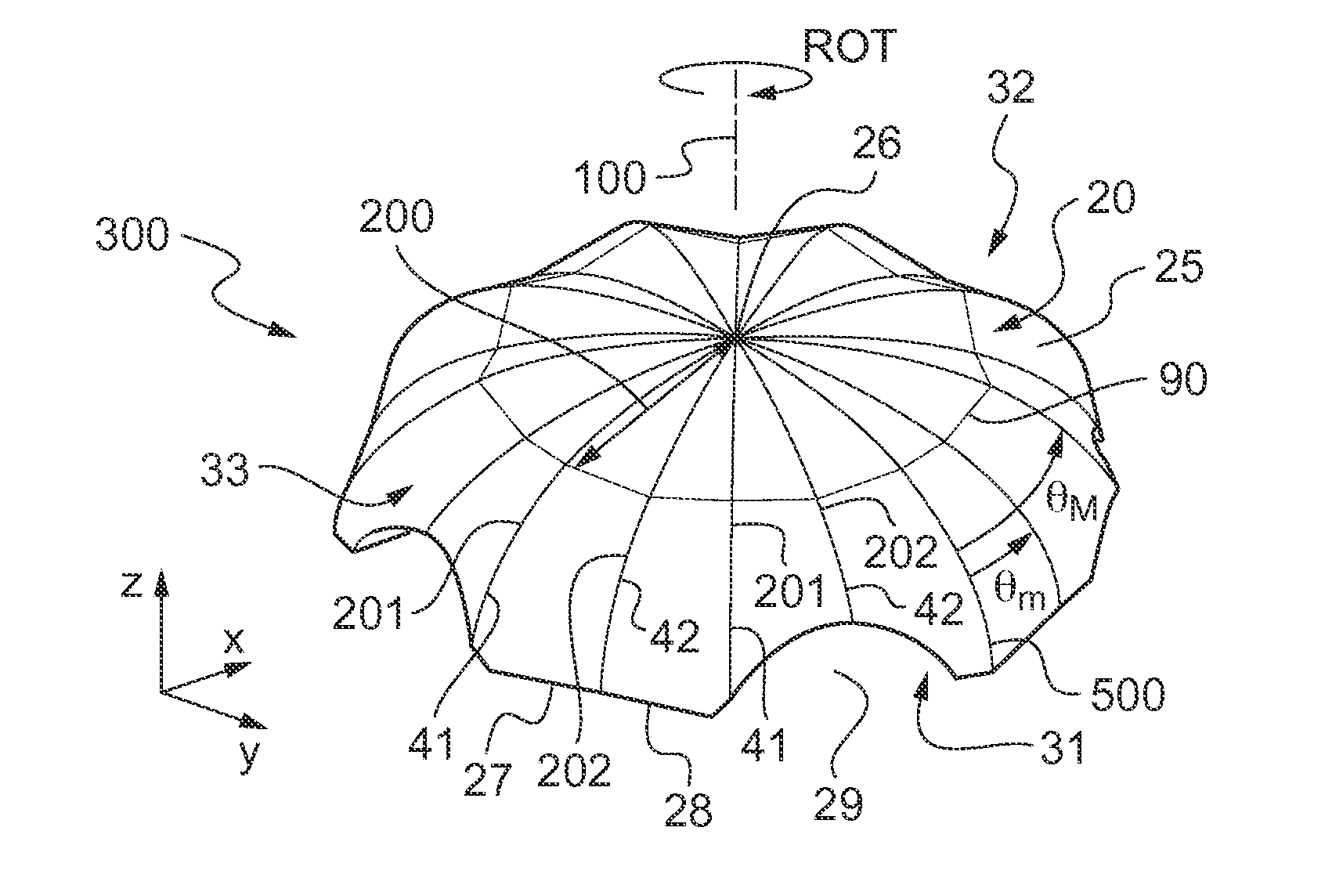
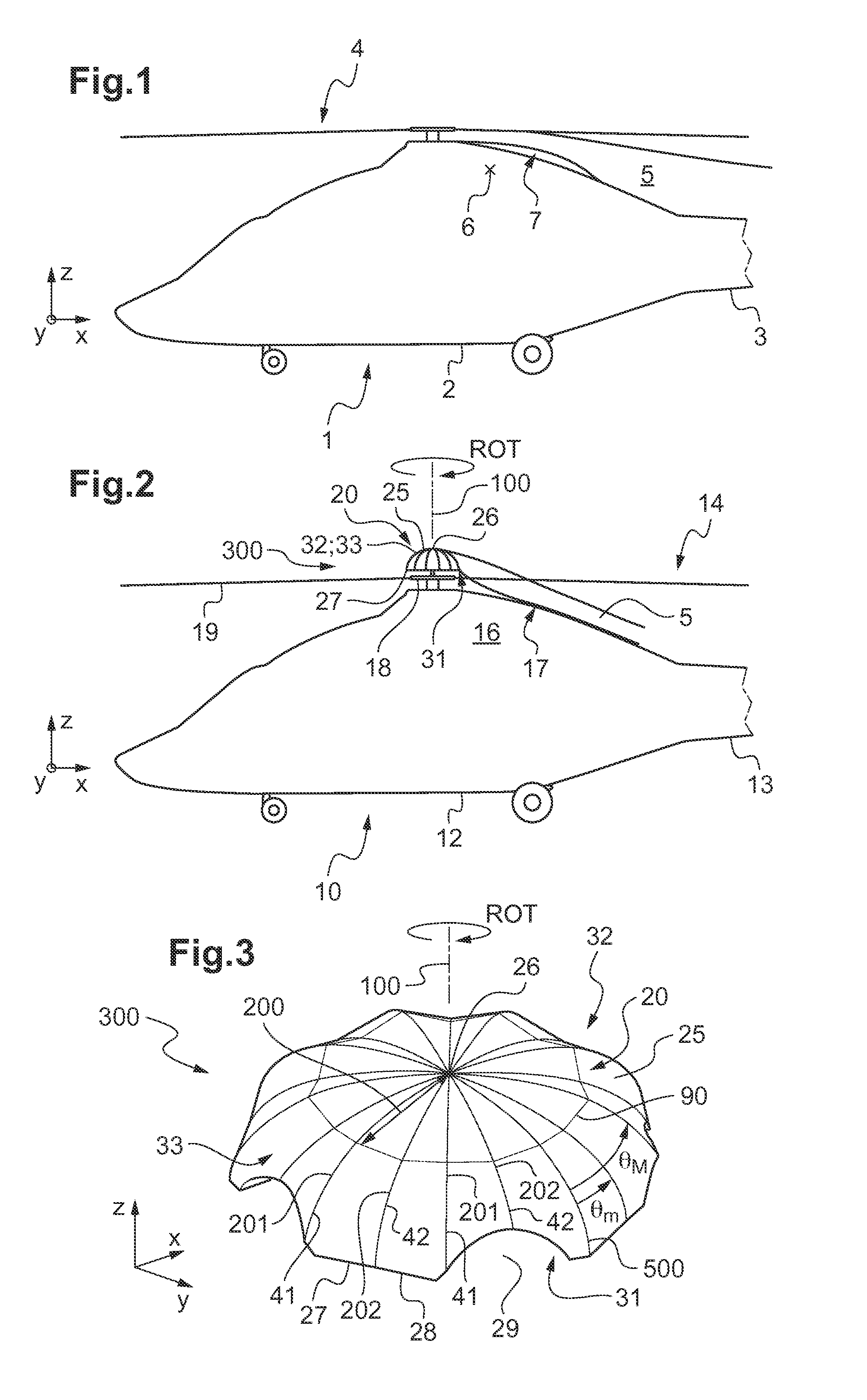
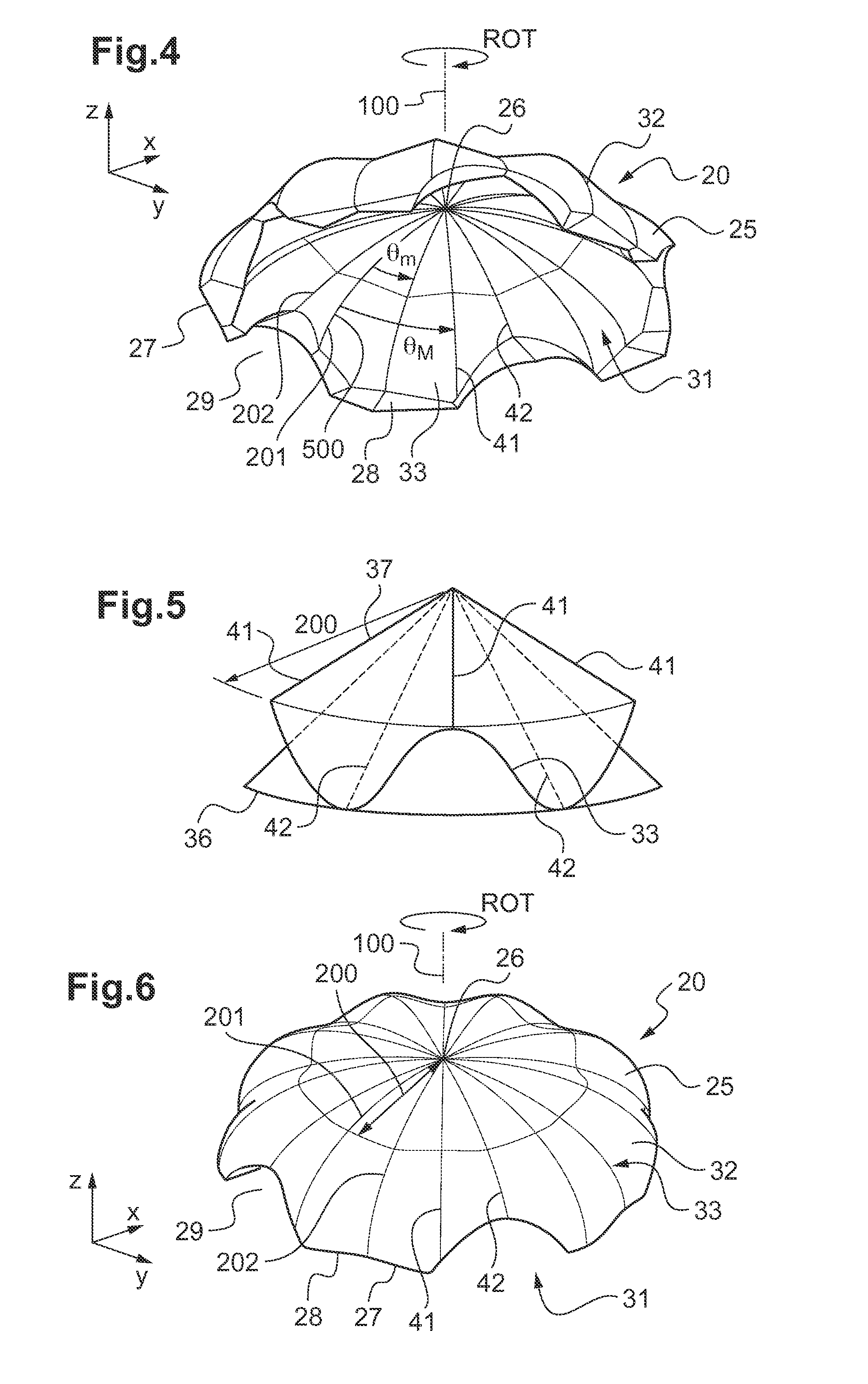
[0128]In the first embodiment shown in FIGS. 3, 4, and 6, at least one of said top and bottom edges 41 and 42 extends radially.

[0129]By way of example, all of the edges extend along radii of the cap.

[0130]In a first variant of the first embodiment, as shown in FIGS. 3 and 4, the thickness between an undulating face and a reference non-undulating middle geometrical surface 50 is determined by the following relationship between a given bottom edge 42 and a given top edge 41 following the given bottom edge 42:

e(r,θ)=e0+Δe(r)(θ-θmθM-θm-12)

where e(r,θ) represents said thickness, e0 is a constant representing a mean thickness, Δe represents a relationship giving a difference between a maximum thickness and a minimum thickness at a radial position “r”, “θ” represents an azimuth position between said given bottom edge 42 and said given top edge 41, “θm” represents an azimuth position of said given bottom edge 42 relative to a reference radius 500, and “θM” represents an azimuth position of ...

second embodiment

[0133]In a second embodiment shown in FIGS. 8 and 9, at least one of said top and bottom edges 41 and 42 does not extend along a radius of the cap 25.

[0134]For example, at least one edge 40 presents a convex shape that is convex pointing 80 in the direction of rotation ROT of the dome 20.

[0135]In a first variant of the second embodiment, as shown in FIG. 8, the thickness between an undulating face and a reference non-undulating middle geometrical surface 50 is determined by the following relationship between a given bottom edge 42 and a given top edge 41 following the given bottom edge 42:

e(r,θ)=e0+Δe(r)(θ-θm(r)θM(r)-θm(r)-12)

where e(r,θ) represents said thickness, e0 is a constant representing a mean thickness, Δe represents a relationship giving a difference between a maximum thickness and a minimum thickness at a radial position “r”, “θ” represents an azimuth position between said given bottom edge 42 and said given top edge 41, “θm(r)” represents a relationship giving an azimuth...


PUM


Abstract

A dome for a rotor of a rotorcraft, the dome comprising a cap extending radially from an axis of rotation in elevation towards a periphery and in azimuth over 360 degrees, the cap extending in thickness from a bottom face for facing a hub of the rotor towards a top face above the bottom face. At least one of the top and bottom faces is an undulating face that undulates at least in azimuth between the periphery and the axis of rotation in elevation, by including in azimuth along at least one internal circle a succession of bulges and of recesses.

Description

CROSS REFERENCE TO RELATED APPLICATION[0001]This application claims priority to French patent application No. FR 14 02558 filed on Nov. 14, 2014, the disclosure of which is incorporated in its entirety by reference herein.BACKGROUND OF THE INVENTION[0002](1) Field of the Invention[0003]The present invention relates to a dome for a rotorcraft lift rotor, and also to a rotorcraft provided with such a dome.[0004](2) Description of Related Art[0005]A rotorcraft conventionally includes an airframe extending from a nose to a tail. The tail may comprise a tail boom carrying a tail fin and stabilizers.[0006]The airframe may carry at least one rotor providing the rotorcraft with at least part of its lift, and possibly also with propulsion. Such a rotor is referred to below as a “lift rotor”, and sometimes as a “main rotor” by the person skilled in the art.[0007]The tail also includes a tail fin, sometimes carrying a rotor for controlling yaw movement of the rotorcraft. As a result, this roto...

Claims


Application Information

Patent Timeline
Patent Type & Authority Applications(United States)
IPC IPC(8): B64C27/32B64C27/00
CPCB64C27/32B64C2027/003B64C27/001B64C7/00B64C27/04B64C11/02B64C11/14
Inventor ALFANO, DAVIDDESVIGNE, DAMIENFUKARI, RAPHAEL
Owner EUROCOPTER
Why Eureka
Try Eureka