Feeder and method for feeding components into an assembly line

a technology for components and assembly lines, applied in the direction of total factory control, programme control, instruments, etc., can solve the problems of affecting the assembly process, so as to achieve convenient cleaning and handling, and easy adaptability

Inactive Publication Date: 2018-05-17
SENSATA TECHNOLOGIES INC
View PDF21 Cites 0 Cited by
  • Summary
  • Abstract
  • Description
  • Claims
  • Application Information

AI Technical Summary

Benefits of technology

[0006]The subject disclosure overcomes the drawbacks of the prior art by providing a feeder and method for feeding components into an assembly line that is simplified, inexpensive, and easily adaptable. Further, the subject disclosure provides a feeder and method for feeding components into an assembly line that requires limited tuning and is easy to clean and handle.

Problems solved by technology

Vibratory feeders of any kind need to be carefully tuned based on the mass, surface finish, and geometry of the parts being fed and tend to be expensive and loud.
The vibrations can also transfer to other parts of the automation equipment and cause problems unless steps are taken to isolate those vibrations.
This can cause a large loss of parts during lot changeover because all the parts in the queue must be discarded.
It also means a single jam will stop the assembly process.
Feeders with multiple actuators, such as step feeders, are inherently more complex due to the added parts and control systems required for their successful operation.
Although step feeders are less prone to jamming and require less tuning than vibratory feeders, step feeders struggle with very small parts because small parts are more difficult to isolate and transfer between the step and conveyor belt.
The small crevices and corners present on these feeders combined with the multitude of surfaces that contact the part makes cleaning and purging these feeders time consuming, which increases the cost of capacity for an assembly line.
It also makes it more difficult to identify the problem if parts get damaged or do not feed well.
Further, vision-guided pick and place operations are becoming increasingly pervasive in modern assembly lines and commercially available feeding solutions are not necessarily best equipped to handle the changing demands of these operations.
Existing feeding options can be expensive, require precise tuning and adjustment, and are not easily adaptable to changes in components.

Method used


Image

  • Feeder and method for feeding components into an assembly line
  • Feeder and method for feeding components into an assembly line
  • Feeder and method for feeding components into an assembly line

Examples


Embodiment Construction

[0022]The subject technology overcomes many of the prior art problems associated with feeding components into a component assembly line. The advantages, and other features of the systems and methods disclosed herein, will become more readily apparent to those having ordinary skill in the art from the following detailed description of certain preferred embodiments taken in conjunction with the drawings which set forth representative embodiments of the present invention.

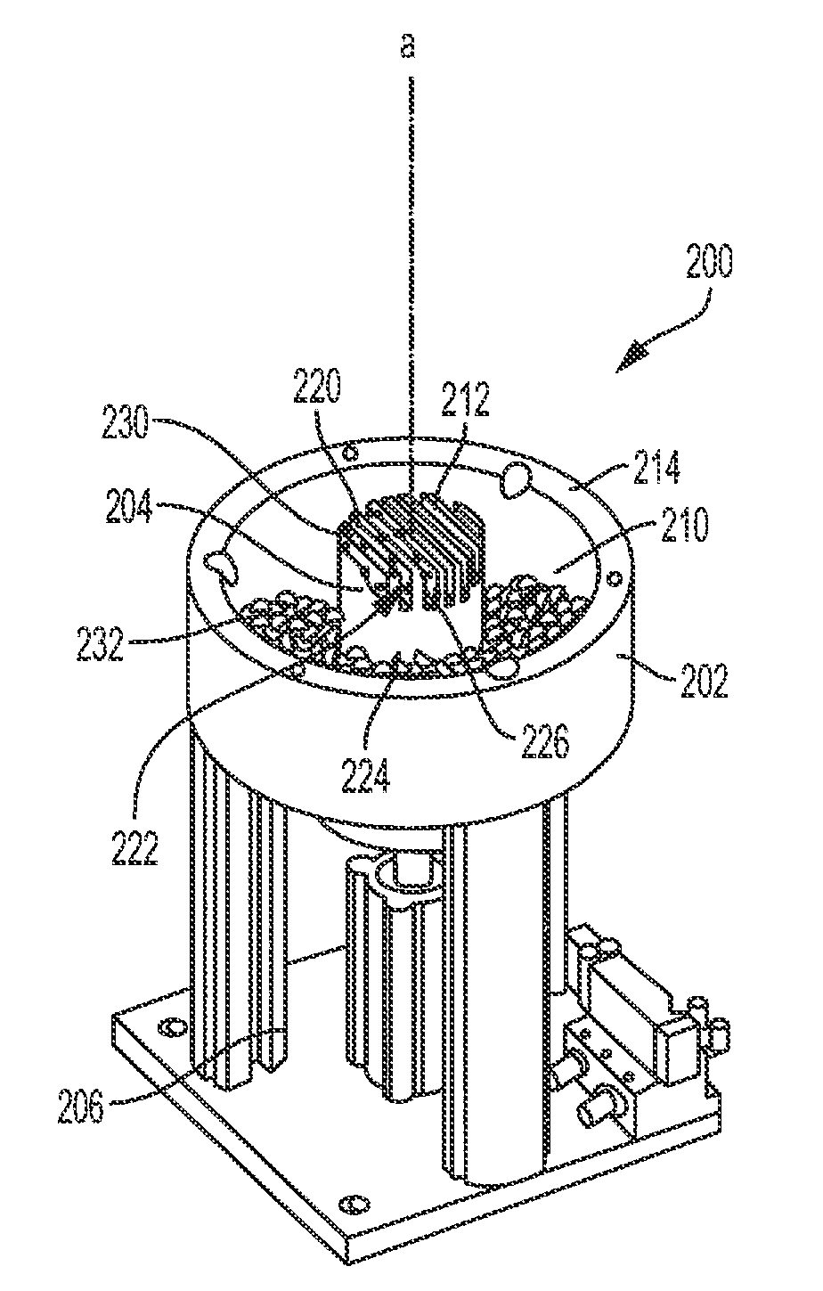
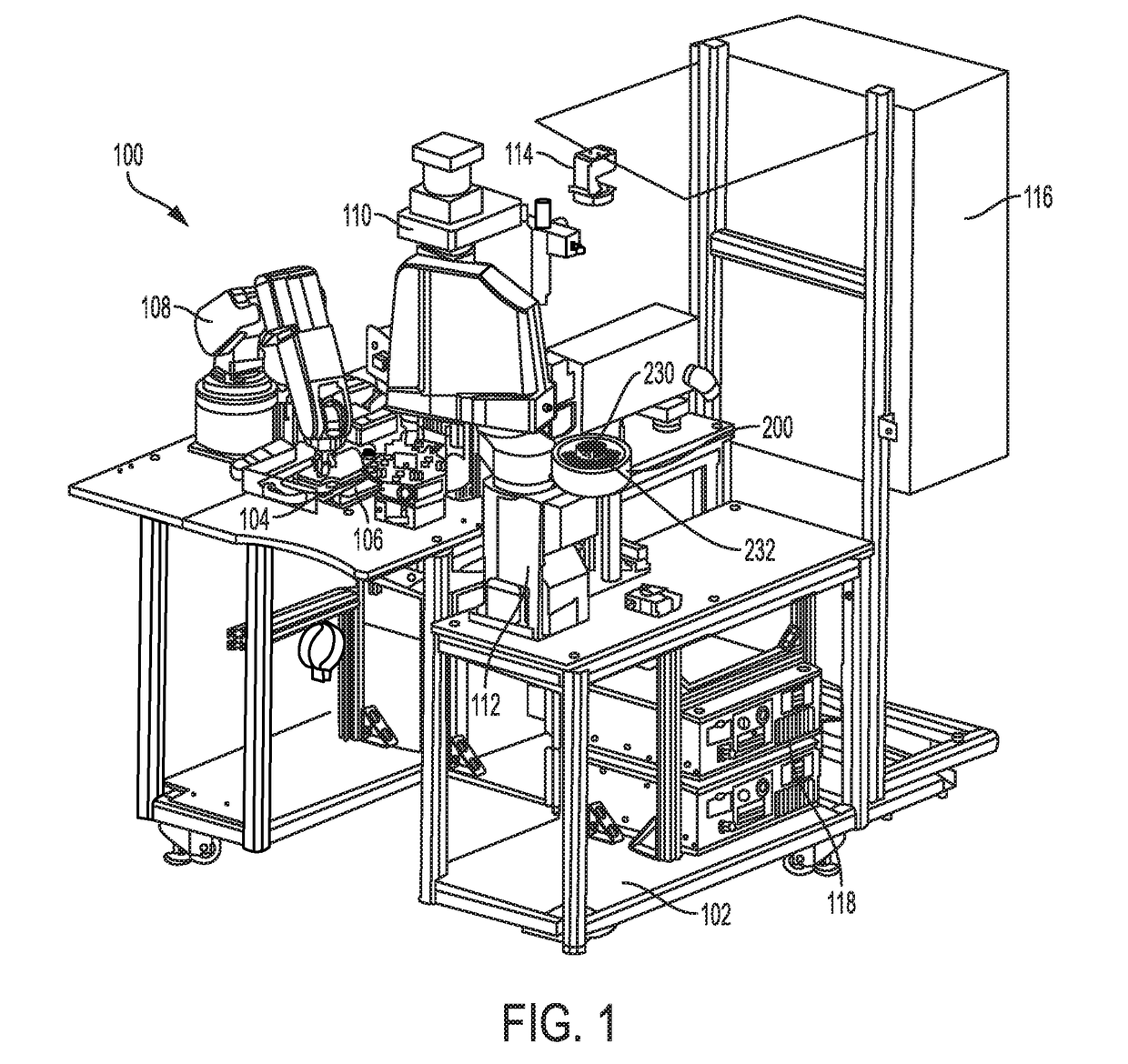
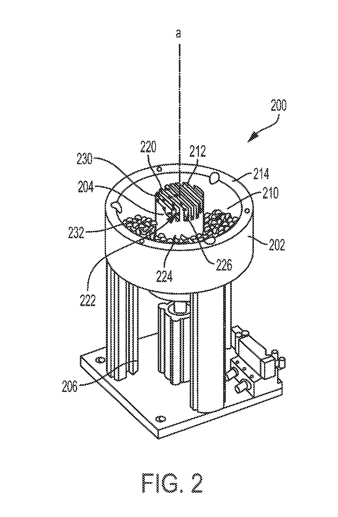
[0023]Referring now to FIG. 1, a work station for a component assembly line in accordance with the subject disclosure is shown generally at 100. The work station 100 acts to bring together two components (not shown) for assembly by welding. The work station 100 includes a two-part assembly line platform 102 for supporting a first component feeder 104. The first component feeder 104 includes a tray 106 of first components. A first robotic arm 108 transfers the first components between the tray 106 and a welding station ...


PUM


Abstract

A system for presenting isolated components to an assembly line over a plurality of cycles includes a container configured to direct components towards a central axis. An elongated pedestal within the container has ribs which define an upper surface and a plurality of channels. The pedestal is reciprocally mounted to move along the central axis, and isolates components during each cycle. The isolated components are transferred to an assembly line. The number of isolated components of each cycle is measured and the value stored. A threshold value is calculated based on a number of stored values. A running average of the quantity of isolated components for a number of cycles can then be compared to the threshold to determine when to refill the component container.

Description

FIELD OF THE INVENTION[0001]The subject disclosure relates to component assembly lines, and more particularly to the improved feeding of components into a component assembly line.BACKGROUND OF THE INVENTION[0002]Automatically feeding bulk-packaged components to assembly machines is the hallmark of an efficient manufacturing process. Vibratory bowl feeders, carpet feeders, step feeders, centrifugal feeders, and systems using multiple actuators have been used to separate and orient bulk-fed components.[0003]Vibratory feeders of any kind need to be carefully tuned based on the mass, surface finish, and geometry of the parts being fed and tend to be expensive and loud. The vibrations can also transfer to other parts of the automation equipment and cause problems unless steps are taken to isolate those vibrations. When the feeder gets dirty, or if changes of any kind are made to the parts being fed, the feeder needs to be re-tuned by a specialist. These types of feeders also rely on the ...

Claims


Application Information

Patent Timeline
Patent Type & Authority Applications(United States)
IPC IPC(8): B65G47/14B65G47/90B25J9/16
CPCB65G47/1442B25J9/1661B25J9/1697B65G47/905B23P19/001B65G47/1471G05B2219/31028G05B2219/50386Y02P90/02B65G47/12
Inventor RYDER, MATTHEW
Owner SENSATA TECHNOLOGIES INC
Why Eureka
Try Eureka