Combustor arrangement

a combustor and arrangement technology, applied in the field of combustor, can solve problems such as flashback of combustion flames, and achieve the effects of reducing or eliminating flame reverse flow, improving combustion dynamics, and stabilizing flame location within the combustor

Active Publication Date: 2018-05-17
SIEMENS ENERGY GLOBAL GMBH & CO KG
View PDF16 Cites 3 Cited by
  • Summary
  • Abstract
  • Description
  • Claims
  • Application Information

AI Technical Summary

Benefits of technology

[0004]One objective of the present invention is to reduce or eliminate flame reverse flow and particularly when using hydrogen as part of the fuel mixture. Another objective is to stabilize flame location within the combustor. Another objective is to improve combustion dynamics and reduce pressure fluctuations in the combustor and neighbouring engine architecture. Another objective is to reduce emissions such as nitrous oxides and sulphur oxides. Another objective is to improve the life of components such as a pilot surface by positioning the combustion flames further downstream.

Problems solved by technology

However, the presence of hydrogen can cause the combustion flame to flashback into the pre-chamber and swirler.

Method used


Image

  • Combustor arrangement
  • Combustor arrangement
  • Combustor arrangement

Examples


Embodiment Construction

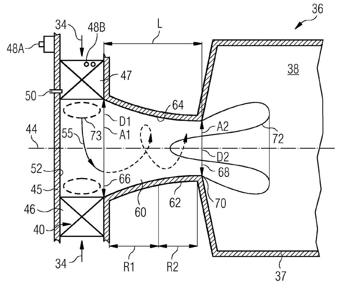
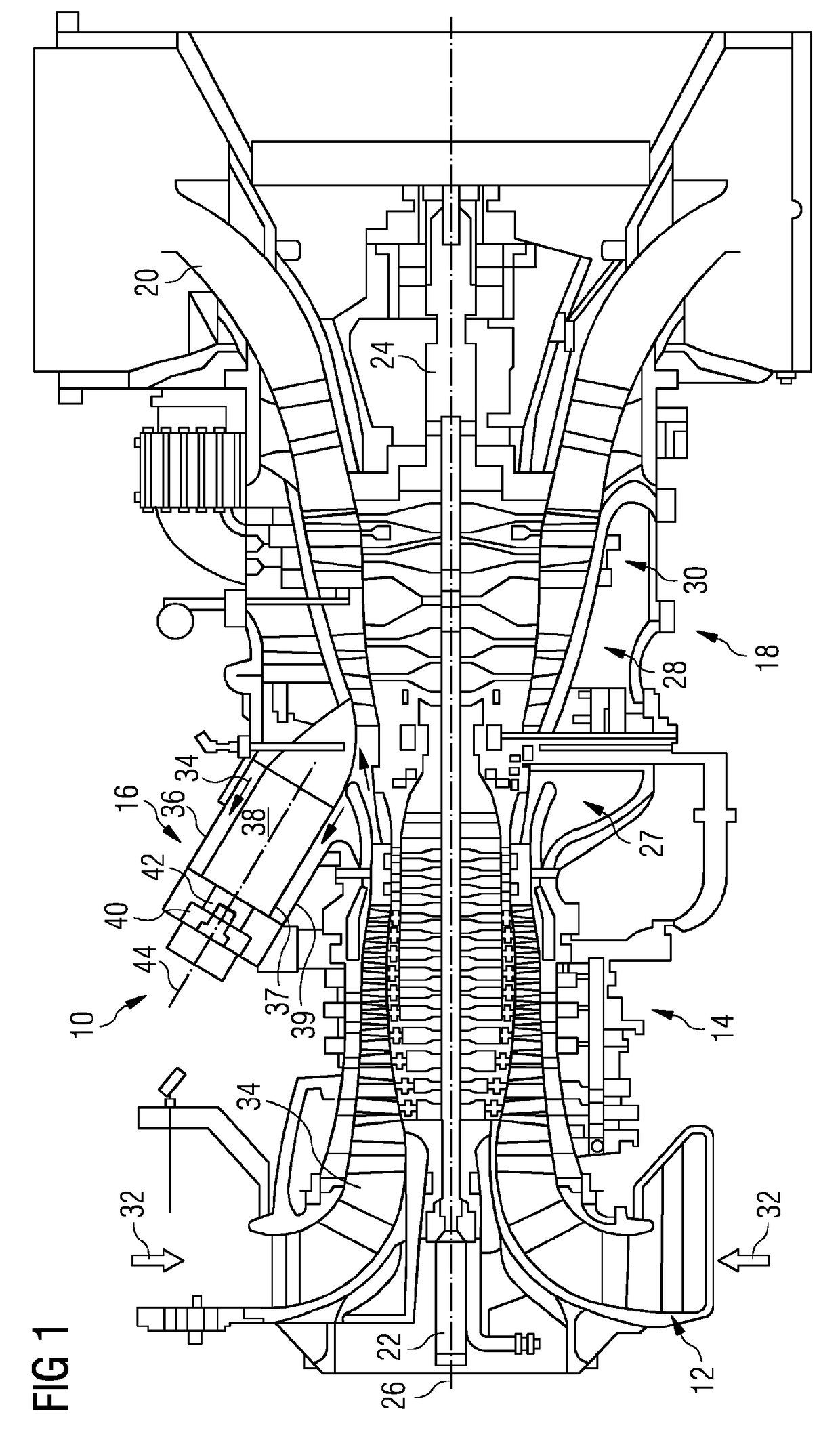
[0026]FIG. 1 is a schematic illustration of a general arrangement of a turbine engine 10 having an inlet 12, a compressor 14, a combustor system 16, a turbine system 18, an exhaust duct 20 and a twin-shaft arrangement 22, 24. The turbine engine 10 is generally arranged about an axis 26 which for rotating components is their rotational axis. The shafts of the twin-shaft arrangement 22, 24 may have the same or opposite directions of rotation. The combustor system 16 comprises an annular array of combustor units 36, only one of which is shown. In one example, there are six combustor units evenly spaced about the engine. The turbine system 18 includes a high-pressure turbine 28 drivingly connected to the compressor 14 by a first shaft 22 of the twin-shaft arrangement. The turbine system 18 also includes a low-pressure turbine 30 drivingly connected to a load (not shown) via a second shaft 24 of the twin-shaft arrangement.

[0027]The terms radial, circumferential and axial are with respect...


PUM


Abstract

A combustor for a gas turbine engine having a central axis about which is arranged in flow sequence a radial swirler, a pre-chamber partly defined by a wall and a combustion chamber. The radial swirler has a base plate having an annular array of vanes and fuel injectors arranged to direct an air/fuel mixture radially inwardly and tangentially to create a vortex that flows through the pre-chamber and into the combustion chamber. The pre-chamber has a portion which is convergent in a downstream direction.

Description

CROSS REFERENCE TO RELATED APPLICATIONS[0001]This application is the US National Stage of International Application No. PCT / EP2016 / 061700 filed May 24, 2016, and claims the benefit thereof. The International Application claims the benefit of European Application No. EP15169977 filed May 29, 2015. All of the applications are incorporated by reference herein in their entirety.FIELD OF INVENTION[0002]The present invention relates to a combustor for a gas turbine and in particular a pre-chamber of the combustor.BACKGROUND OF INVENTION[0003]In a gas turbine Dry Low Emissions (DLE) combustion system, it is possible to burn a small amount, e.g. 5% by volume, of hydrogen with natural gas. However, the presence of hydrogen can cause the combustion flame to flashback into the pre-chamber and swirler. This is primarily due to the configuration of the radial swirler burner with main gas fuel injection in the radial swirler slots at two different locations. Aerodynamics in the central region of ...

Claims


Application Information

Patent Timeline
Patent Type & Authority Applications(United States)
IPC IPC(8): F23R3/28F23R3/14
CPCF23R3/286F23R3/14F23R2900/00002F23C2900/03005F23C2900/9901
Inventor SADASIVUNI, SURESH
Owner SIEMENS ENERGY GLOBAL GMBH & CO KG
Why Eureka
Try Eureka