Supercharge Your Innovation With Domain-Expert AI Agents!

Magnetizing device for magnetic encoder

a magnetic encoder and magnetic technology, applied in the direction of transformer/inductance details, magnetic bodies, instruments, etc., can solve the problems of increased chance of magnetic saturation, reduced magnetization strength, and difficulty in precision magnetization, so as to facilitate magnetization of a plurality of magnetic encoder tracks, reduce magnetic resistance, and reduce the effect of dimension

Active Publication Date: 2018-05-17
NTN CORP
View PDF0 Cites 2 Cited by
  • Summary
  • Abstract
  • Description
  • Claims
  • Application Information

AI Technical Summary

Benefits of technology

The patent text explains that there is a balance between magnetic resistance and magnetization strength, and that a narrow gap between the magnetic shield and the magnetization head plays an important role in achieving good balance. If the gap is too narrow, magnetic resistance decreases, allowing magnetic flux to flow freely and decreasing magnetization strength. On the other hand, if the gap is too wide, less shielding effect is available, making it difficult to perform magnetization with precision. By designing the gap to be between 0.5 mm and 2 mm, the magnetic resistance can be maintained at an appropriate level.

Problems solved by technology

However, this also results in corresponding reduction of magnetic flux that is introduced into a magnetic encoder track 3 or 4, thereby leading to decreased magnetization strength.
Conversely, greater magnetic resistance between the magnetization head 6a and the magnetic shield 11 leads to an increased chance of the occurrence of magnetic saturation at the magnetic shield 11, resulting in less shielding effect that makes it difficult to perform magnetization with precision.
As such, it is challenging to provide a suitable magnetic shield 11 that can achieve good balance between magnetization strength and magnetization precision.

Method used


Image

  • Magnetizing device for magnetic encoder
  • Magnetizing device for magnetic encoder
  • Magnetizing device for magnetic encoder

Examples


Embodiment Construction

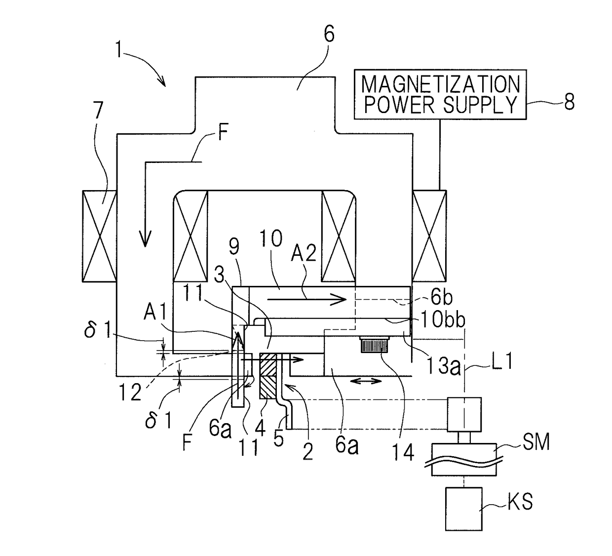
[0043]One embodiment of the present invention will be described in connection with FIG. 1A and FIG. 1B to FIG. 8.

[0044]A magnetizing device in accordance with embodiments of the present invention may be employed, for example, as a magnetizing device for a magnetic encoder, where the magnetic encoder is intended to be used for detection of rotation or a rotational angle of a variety of mechanical components. The description that follows also includes a description of a magnetic encoder and of a method for magnetizing the magnetic encoder.

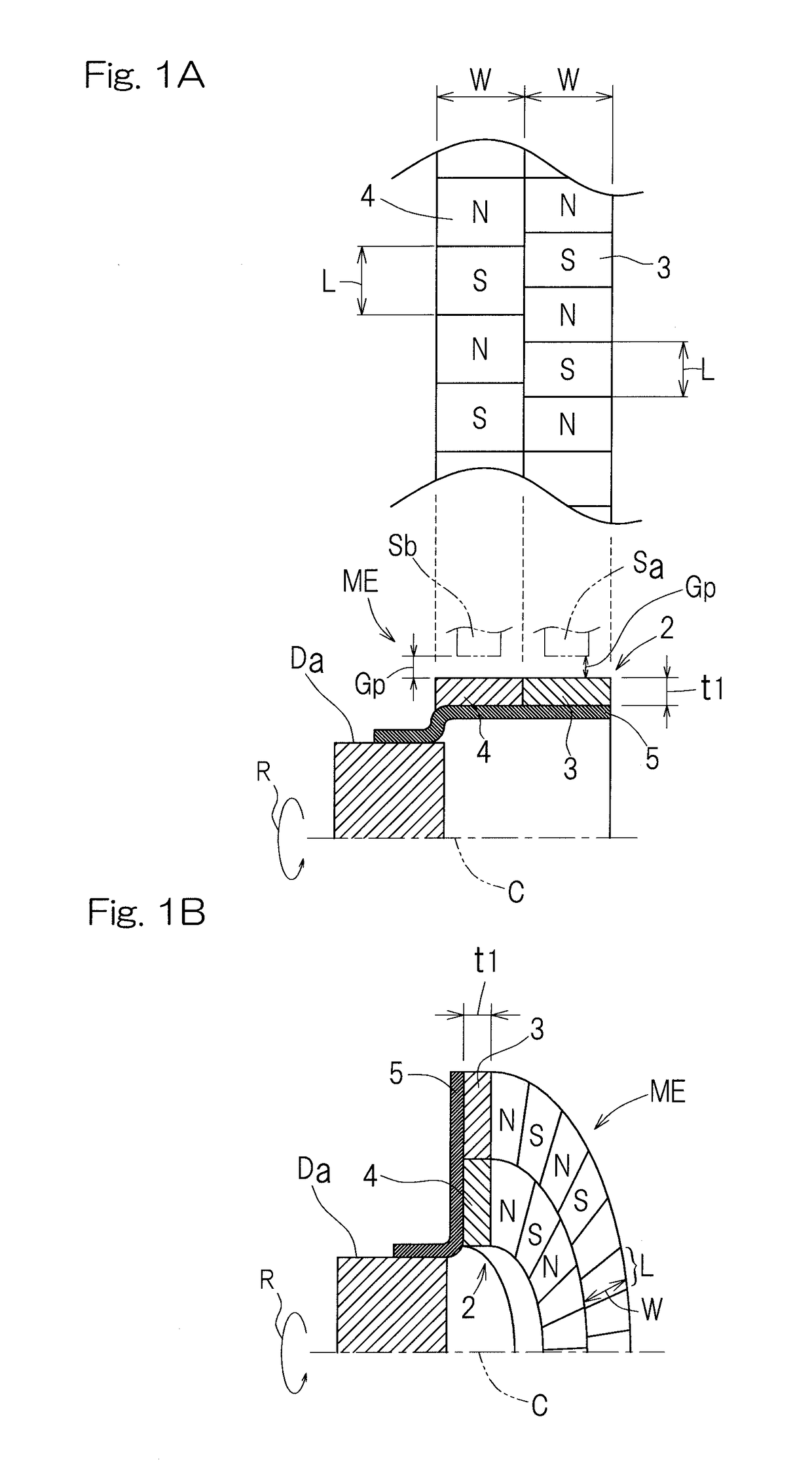
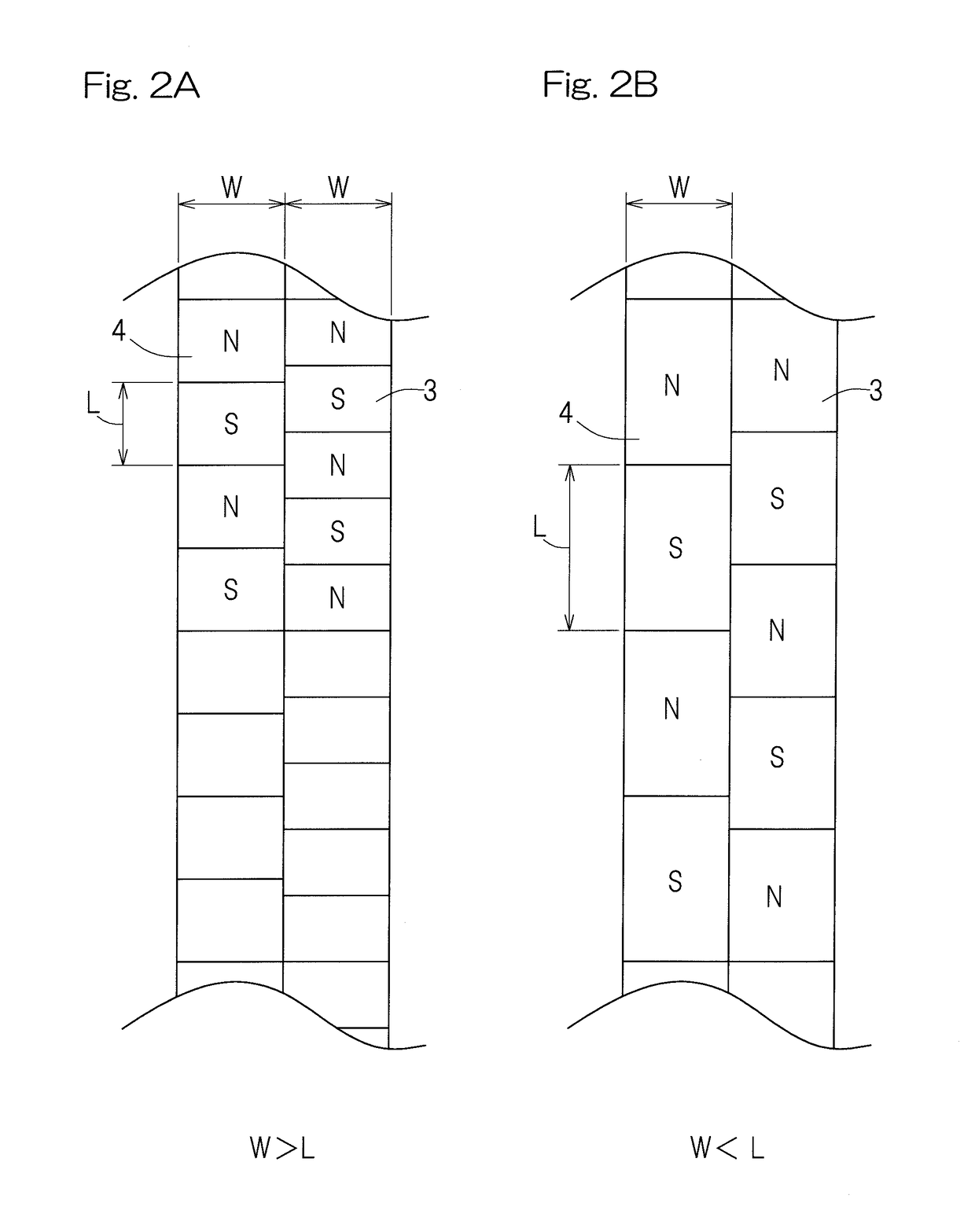
[0045]As shown in FIG. 3A and FIG. 3B, the magnetizing device 1 is operable to magnetize an annular magnetic body 2, such that the annular magnetic body 2 is magnetized with one magnetic pole at a time by causing the annular magnetic body 2 to rotate about an axis L1 of rotation thereof, thereby producing a magnetic encoder ME such as, for example, those illustrated in FIG. 1A and FIG. 1B. The annular magnetic body 2 integrally has a plurality of unm...


PUM

PropertyMeasurementUnit
lengthaaaaaaaaaa
lengthaaaaaaaaaa
widthaaaaaaaaaa

Abstract

A magnetizing device includes a magnetization yoke including a pair of magnetization heads confronting each other through a magnetic gap, an excitation coil wound around the magnetization yoke, and a magnetization power supply that supplies a magnetizing current to the excitation coil to generate magnetic flux between the magnetization heads. A magnetic shield is provided on the magnetization yoke. The magnetic shield is spaced apart from one of the magnetization heads with a gap being formed therebetween along a direction in which the plurality of magnetic encoder tracks are arranged. The magnetic shield blocks a flow of magnetic flux that is present outside a defined extension of a flow of the magnetic flux between the pair of magnetization heads. The magnetic shield is of such a geometry that a thickness thereof progressively decreases towards the one of the magnetization heads.

Description

CROSS REFERENCE TO THE RELATED APPLICATION[0001]This application is based on and claims Convention priority to Japanese patent application No. 2015-083257, filed Apr. 15, 2015, the entire disclosure of which is herein incorporated by reference as a part of this application.BACKGROUND OF THE INVENTIONField of the Invention[0002]The present invention relates to a magnetizing device for a magnetic encoder, where the magnetic encoder is intended to be used for detection of rotation or a rotational angle of a variety of mechanical components.Description of Related Art[0003]Patent Document 1 discloses a technique for manufacturing a magnetic encoder that is magnetized with a plurality of magnetic poles. Also, Patent Document 2 discloses, as a development of the technique disclosed in the Patent Document 1, a technique for magnetizing a plurality of adjoining magnetic encoder tracks with precision. More specifically, the technique disclosed in the Patent Document 2 attempts to increase mag...

Claims


Application Information

Patent Timeline
Patent Type & Authority Applications(United States)
IPC IPC(8): H01F13/00H01F27/36
CPCH01F13/003H01F27/365H01F13/00H01F27/366G01D5/2451H01F27/36
Inventor TAKAHASHI, TORUUENO, SHINTAROU
Owner NTN CORP
Features
  • R&D
  • Intellectual Property
  • Life Sciences
  • Materials
  • Tech Scout
  • Unparalleled Data Quality
  • Higher Quality Content
  • 60% Fewer Hallucinations
Learn More