Voltage source for modulated DC voltages

a voltage source and modulation technology, applied in the direction of dc-dc conversion, power conversion systems, amplifiers with semiconductor devices/discharge tubes, etc., can solve the problems of poor efficiency of switched-mode power supplies, inability to realize controlled systems with good linearity, and virtually impossible to modulate output voltage even at low frequencies, so as to reduce harmonics of modulated dc signals, low resonance, and work with only very small losses

Pending Publication Date: 2018-05-17
IIE
View PDF4 Cites 5 Cited by
  • Summary
  • Abstract
  • Description
  • Claims
  • Application Information

AI Technical Summary

Benefits of technology

[0021]To reduce harmonics on the modulated DC signal, it is particularly advantageous to provide a filter circuit having a resonance coil and a resonance capacitor, wherein the filter circuit is arranged parallel to the smoothing capacitor. The filter circuit is tuned to the switching frequency of the electronic switching elements and thus ensures minimization of the capacitive load of the system, since the smoothing capacitor can be made very small in this way.
[0022]To operate the circuit according to the invention with low phase shifts and distortions, the coordination between the coil and the smoothing capacitor plays a significant role. Particularly advantageous is the coordination when the coil and the smoothing capacitor are tuned to a resonance frequency that is between one third and one fifteenth of the frequency that is used to switch the first and the second electronic switching element. For example, at a switching frequency of 300 kHz, the resonance frequency of the coil and the smoothing capacitor should consequently be between 20 and 100 kHz. In particular, it should be between one-sixth and one-twelfth of the switching frequency, in the above example, thus between about 25 and 50 kHz. This can ensure that the circuit is very low in resonance and loaded with the smallest possible capacitive reactive currents and thereby works with only very small losses.
[0023]Particularly advantageous, a high-frequency amplifier as a load is provided, which is additionally supplied with a high-frequency signal from an oscillator. In this way, one obtains an amplitude-modulated high-frequency signal, which was generated from the original reference signal. The system responds very dynamically to changes in the frequency of the reference signal and works with extremely low losses and with high cost efficiency.
[0024]The voltage source is designed as a switched-mode power supply with an output power of more than one kilowatt. In particular, switched-mode power supplies with a power between one and fifty kilowatts can be realized in this way with low costs and very low losses. When using a regulated DC voltage source, it is readily possible in the stated power range to dispense with a regulation that controls the electronic switching elements using a complex control loop.

Problems solved by technology

For a voltage modulation of such a source, the capacitive reactive current would be many times greater than the load current, so that a modulation of the output voltage—even at low frequencies—would be virtually impossible.
In practical applications, it has been shown that—due to the latency times resulting from internal processing—it is not possible to realize controlled systems with good linearity without natural oscillations over the entire required dynamic range and load range with reasonable effort while maintaining economic aspects.
The poor efficiency of these switched-mode power supplies is also due to the regulation used.
The regulation results in large latency times that lead to oscillations.
In this case, a large amount of energy is not converted into power, but converted into unneeded heat.
This heat, in turn, must be dissipated and destroyed, which, in turn, has a negative effect on the efficiency.

Method used


Image

  • Voltage source for modulated DC voltages
  • Voltage source for modulated DC voltages
  • Voltage source for modulated DC voltages

Examples


Embodiment Construction

[0033]The preferred embodiments of the present invention will now be described with reference to FIGS. 1-7 of the drawings. Identical elements in the figures are designated with the same reference numerals.

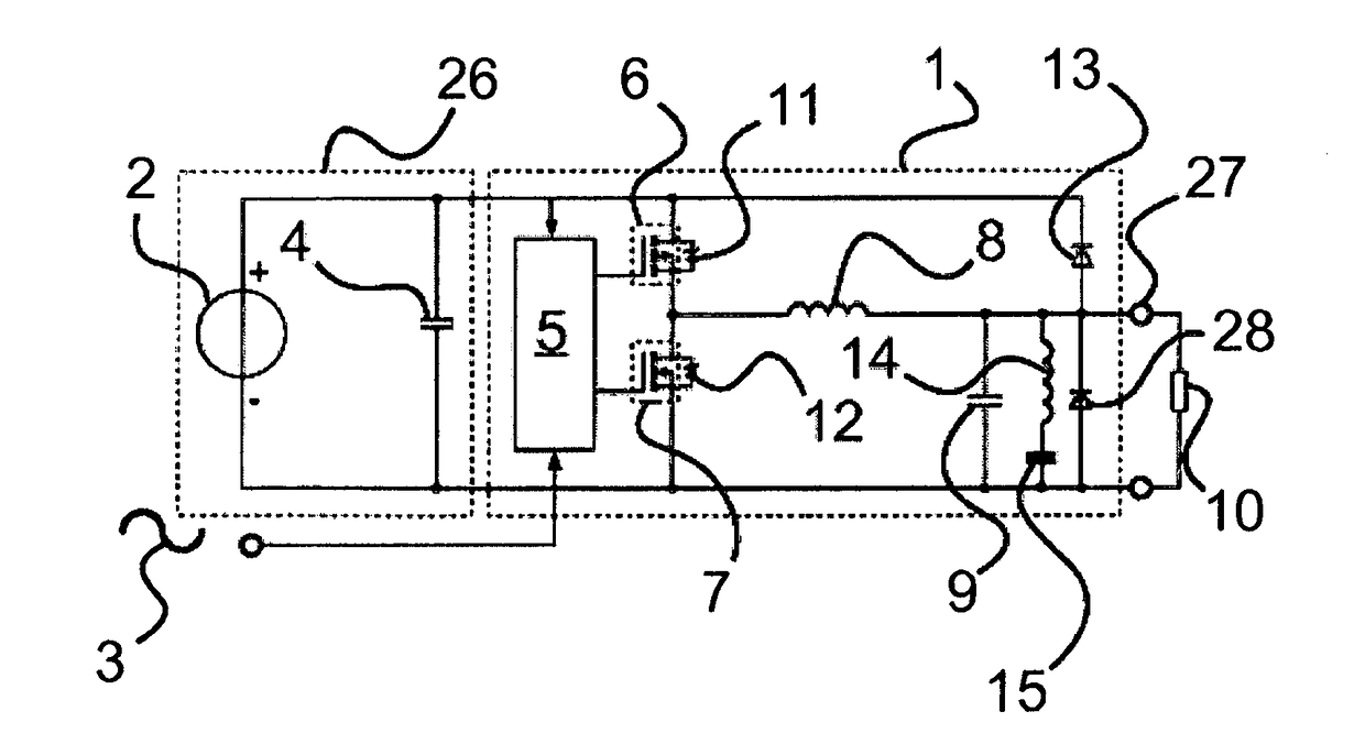
[0034]The reference sign 3 designates the reference signal. This highly dynamically modulated reference signal is to be power-amplified, but remain as unchanged as possible in shape and phase. The reference signal 3 is applied to the controller 5 of the modulator 1.

[0035]The power supply 26 is of a standard design and consists of the static DC voltage source 2 that can handle a great power and the capacitor 4. The capacitor 4 is drawn representative of several capacities, which can absorb occurring voltage peaks and thus protect the DC voltage source 2 against damage. The DC voltage source is a regulated DC voltage source, i.e., a so-called constant-voltage source, which provides a very exact voltage.

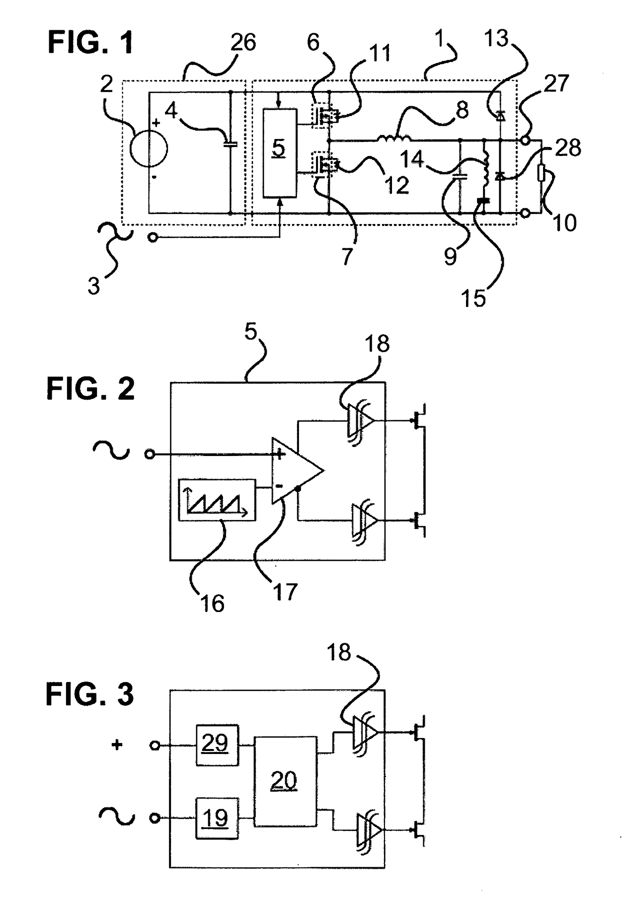
[0036]The modulator 1 has a controller 5. Alternative embodiments of the controll...


PUM


Abstract

A voltage source for modulated DC voltages, operative to amplify the power of a reference signal to keep an output voltage constant, has a static DC voltage source with at least one parallel capacitor. The voltage source includes a first switching element, which is connected in parallel to the static DC voltage source and can be switched on or off by an unregulated controller; a second electronic switching element, which is connected in series to the first electronic switching element and in parallel to the DC voltage source and can be switched on or off by the controller; a coil, which is connected in series with the first electronic switching element and in parallel to the second electronic switching element; a smoothing capacitor, which is connected in series with the coil; and a load, which is connected in parallel to the smoothing capacitor.

Description

BACKGROUND OF THE INVENTION[0001]The invention relates to a voltage source for modulated DC voltages for amplifying the power of a reference signal to keep an output voltage constant.[0002]Modulated DC voltage sources for amplifying a reference signal with a broad frequency band (approximately 1 to 100 kHz) are typically implemented using an amplifier when power between a few kW up to the mid two-digit power range is needed. The amplifier is connected to a constant voltage source.[0003]Standard constant voltage sources are usually equipped with large capacitors at the output. For example, according to the prior art, a switched-mode power supply for an output voltage of 50 V and a power of 3 kW has output capacitors with a total value of 5000 μF. For a voltage modulation of such a source, the capacitive reactive current would be many times greater than the load current, so that a modulation of the output voltage—even at low frequencies—would be virtually impossible.[0004]Attempts hav...

Claims


Application Information

Patent Timeline
Patent Type & Authority Applications(United States)
IPC IPC(8): H02M1/14H02M3/157H02M1/32H02M3/158
CPCH02M1/14H02M3/157H02M1/32H02M3/158H02M3/155H03F3/2173H02M1/322
Inventor KRESS, EKKEHARD
Owner IIE
Why Eureka
Try Eureka