Front-end module

Active Publication Date: 2018-05-17
MURATA MFG CO LTD
View PDF5 Cites 21 Cited by
  • Summary
  • Abstract
  • Description
  • Claims
  • Application Information

AI Technical Summary

Benefits of technology

[0026]Accordingly, the power amplifier circuit and the switch element or filter element are disposed on the same substrate, which can achieve a reduction in the size of the front-end

Problems solved by technology

However, if a traditional multi-band, multi-mode front-end module is used in the so-called carrier aggrega

Method used


Image

  • Front-end module
  • Front-end module
  • Front-end module

Examples


example implementation

[0066](2. Example Implementation)

[0067][2.1 Configuration of Front-End Module according to Example Implementation]

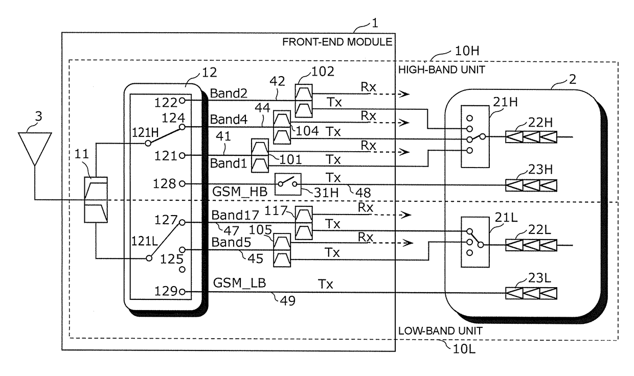
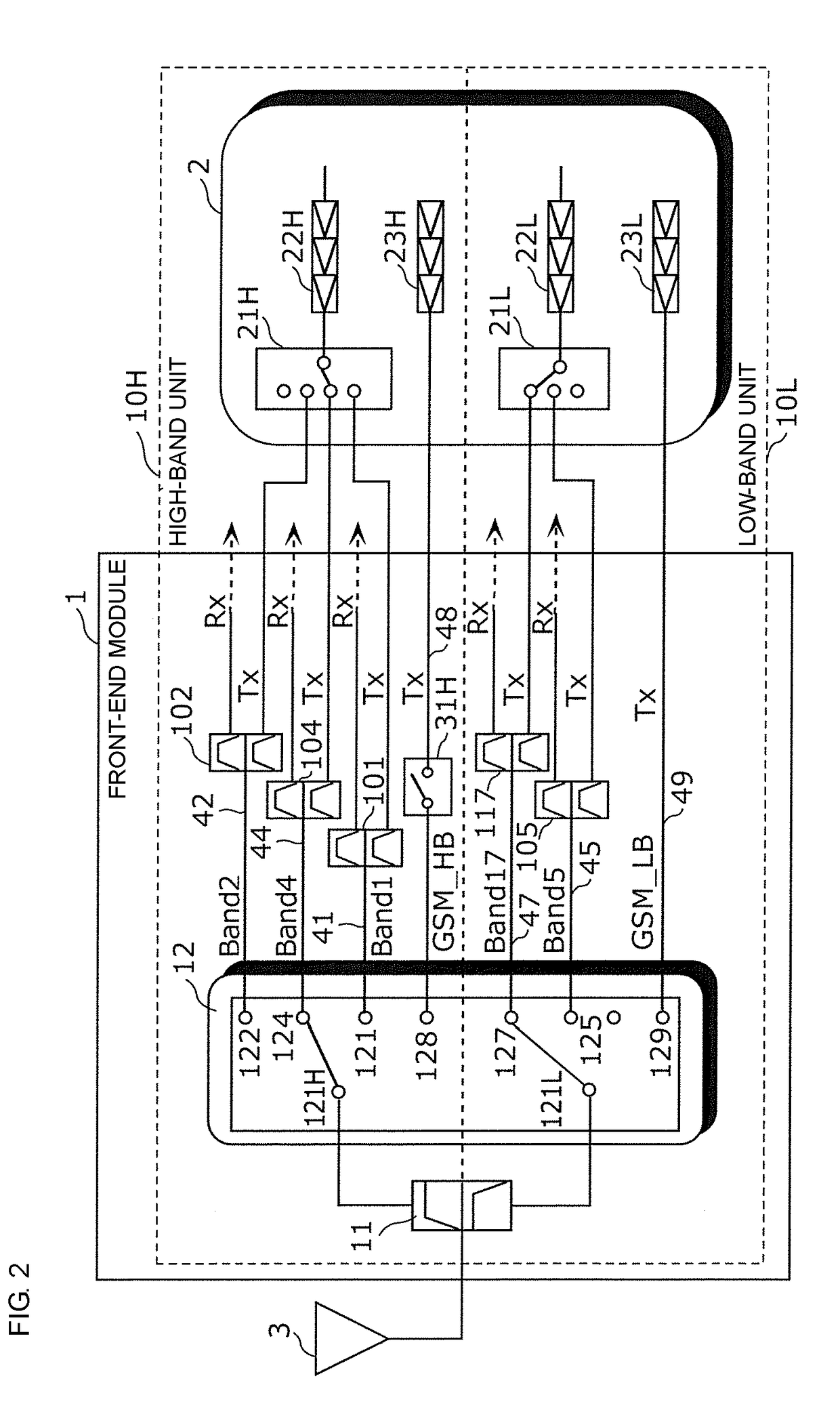
[0068]FIG. 2 is a circuit configuration diagram of a front-end module according to an example implementation. In FIG. 2, a front-end module 1 according to an example implementation, a power amplifier module 2, and an antenna element 3 are illustrated. The front-end module 1, the power amplifier module 2, and the antenna element 3 are disposed at the front end of a multi-mode / multi-band cellular phone, for example.

[0069]The front-end module 1 includes a diplexer 11, an antenna switch module 12, a signal path 41 for selectively propagating a signal of Band 1 (transmission band: 1920 to 1980 MHz, reception band: 2110 to 2170 MHz) conforming to the LTE standard, a signal path 42 for selectively propagating a signal of Band 2 (transmission band: 1850 to 1910 MHz, reception band: 1930 to 1990 MHz) conforming to the LTE standard, a signal path 44 for selectively propagating a s...


PUM


Abstract

A front-end module that uses a carrier aggregation scheme in which Band, which is selected from a low-frequency band group, and Band, which is selected from a high-frequency band group, are used simultaneously for communication includes a plurality of signal paths that connect a power amplifier module to an antenna element, and an antenna switch module that switches connection between the antenna element and the plurality of signal paths. Harmonics of Band have frequencies that are included in Band. The front-end module further includes a switch element disposed in a TDD transmission path.

Description

[0001]This is a continuation of International Application No. PCT / JP2016 / 062294 filed on Apr. 18, 2016 which claims priority from Japanese Patent Application No. 2015-143321 filed on Jul. 17, 2015. The contents of these applications are incorporated herein by reference in their entireties.BACKGROUNDTechnical Field[0002]The present disclosure relates to a front-end module that processes radio-frequency signals.[0003]To support international roaming, improvements in communication speed, and so on, cellular phones are required to support a plurality of frequency bands and radio systems with single terminals (multi-band and multi-mode support).[0004]Patent Document 1 discloses a circuit block diagram of a multi-band (3G / LTE (Long Term Evolution)) front-end module (FIG. 2). As illustrated in FIG. 2, a 3G / LTE system is separated into a high-frequency band group (HB: High Band group) and a low-frequency band group (LB: Low Band group). The high-frequency band group and the low-frequency ba...

Claims


Application Information

Patent Timeline
IPC IPC(8): H04B1/00H04B1/54H04B1/48
CPCH04B1/006H04B1/0057H04B1/54H04B1/48H04B1/0067H04B1/69H04J3/00H04B1/3833H04L5/001H04L5/1469H04L5/0023H04B1/525
Inventor NAGUMO, SHOJIMOTOKI, KANTAHIEJIMA, KEIJI
Owner MURATA MFG CO LTD
Why Eureka
Try Eureka