
Bone fixation screw with deployable anchors

a bone fixation screw and deployable technology, applied in the field of bone fixation devices, can solve the problems of reducing the ability of the screw structure to maintain firm purchase with such bones, significant health detriment to the aging bone fusion population, and financial burden on the u.s. healthcare system, so as to reduce the risk of cement migration, facilitate the deployment of bone anchors, and facilitate fixation

Active Publication Date: 2018-05-24
MIRUS LLC
View PDF0 Cites 0 Cited by
  • Summary
  • Abstract
  • Description
  • Claims
  • Application Information

AI Technical Summary

Benefits of technology

The present invention relates to a bone screw for use in treating osteoporotic spine fractures. The bone screw can be used as a transcortical fixation pellicle screw, which helps take advantage of the most rigid and durable bone in the spine. The anchor system of the bone screw can fixate across the inner and outer cortical bone rim of the pedicle and translate multi-direction forces placed on the screw to the full cortical bone wall, providing better stability and reduced risk of cement migration onto nerve elements. The technical effects of the invention include improved stability and reduced risk of cement migration onto nerve elements.

Problems solved by technology

However, the rapidly growing aging population presents a challenge to effective and durable screw fixation because the increased rigidity of older bones increases pull-out stress on bone screw constructs, while the poor bone quality of osteopenic and osteoporotic patients decreases the ability of screw structures to maintain firm purchase with such bones.
As a result, screw loosening and bone fusion failure occur at nearly ten times the normal rate in elderly and osteoporotic patients, representing a significant health detriment to the aging bone fusion population at large and a financial burden to the U.S. healthcare system.
Despite these advancements, bone screw fixation failures and pseudo arthrosis remain a common complication in the treatment of elderly and osteoporotic patients.
Even when optimal screw thread-inner cortical bone rim purchase is achieved at surgery, the osteoporotic inner cortical rim is often not rigid or durable enough to maintain the desired thread-bone fixation.

Method used


Image

  • Bone fixation screw with deployable anchors
  • Bone fixation screw with deployable anchors
  • Bone fixation screw with deployable anchors

Examples


Embodiment Construction

[0060]While the making and using of various embodiments of the present invention are discussed in detail below, it should be appreciated that the present invention provides many applicable inventive concepts that are embodied in a wide variety of specific contexts. The specific embodiments discussed herein are merely illustrative of specific ways to make and use the invention and do not delimit the scope of the invention.

[0061]To facilitate the understanding of the embodiments described herein, a number of terms are defined below. The terms defined herein have meanings as commonly understood by a person of ordinary skill in the areas relevant to the present invention. Terms such as “a,”“an,” and “the” are not intended to refer to only a singular entity, but rather include the general class of which a specific example may be used for illustration. The terminology herein is used to describe specific embodiments of the invention, but their usage does not delimit the invention, except a...


PUM


Abstract

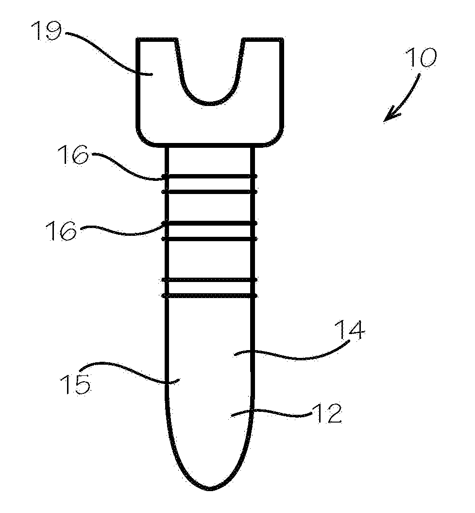
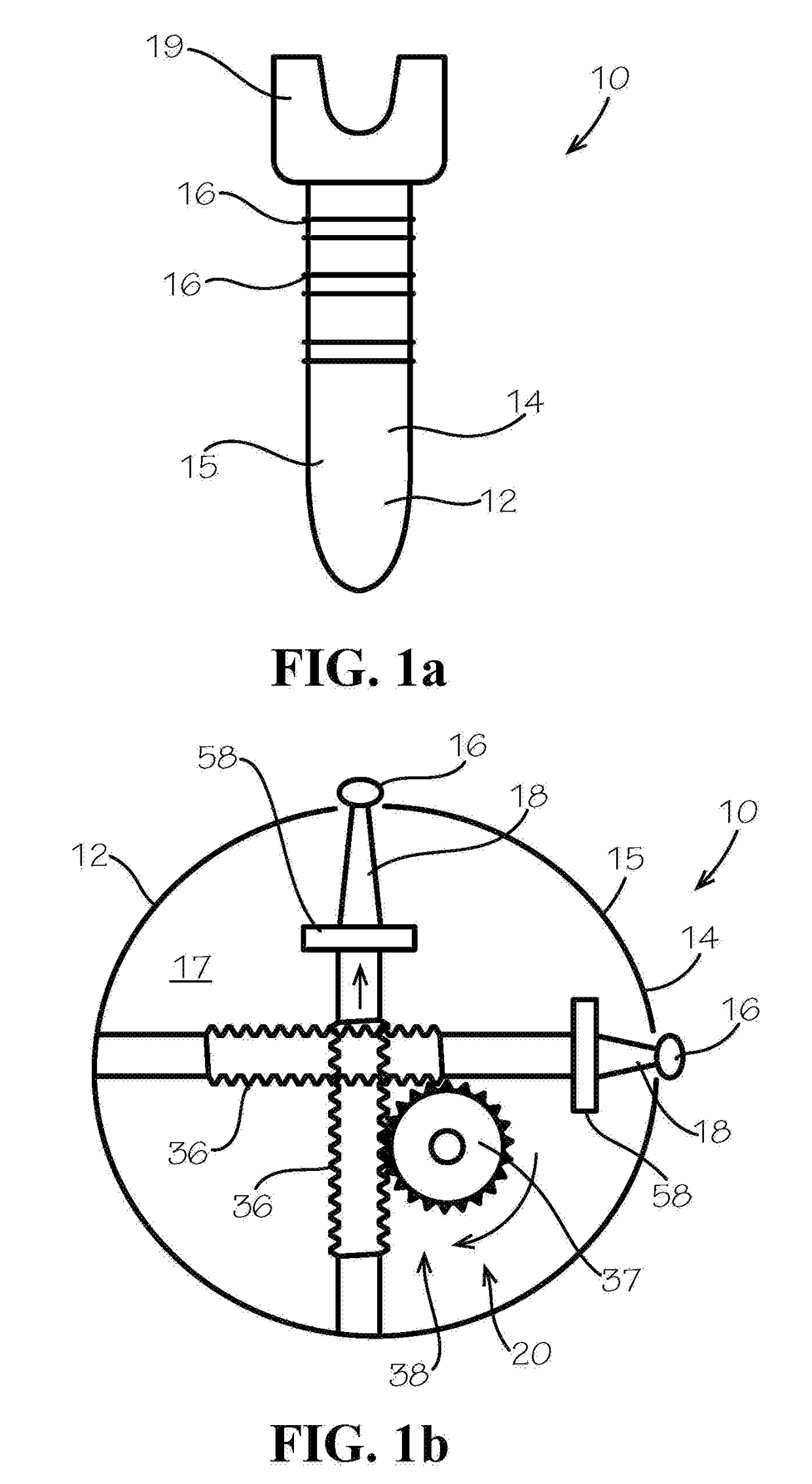
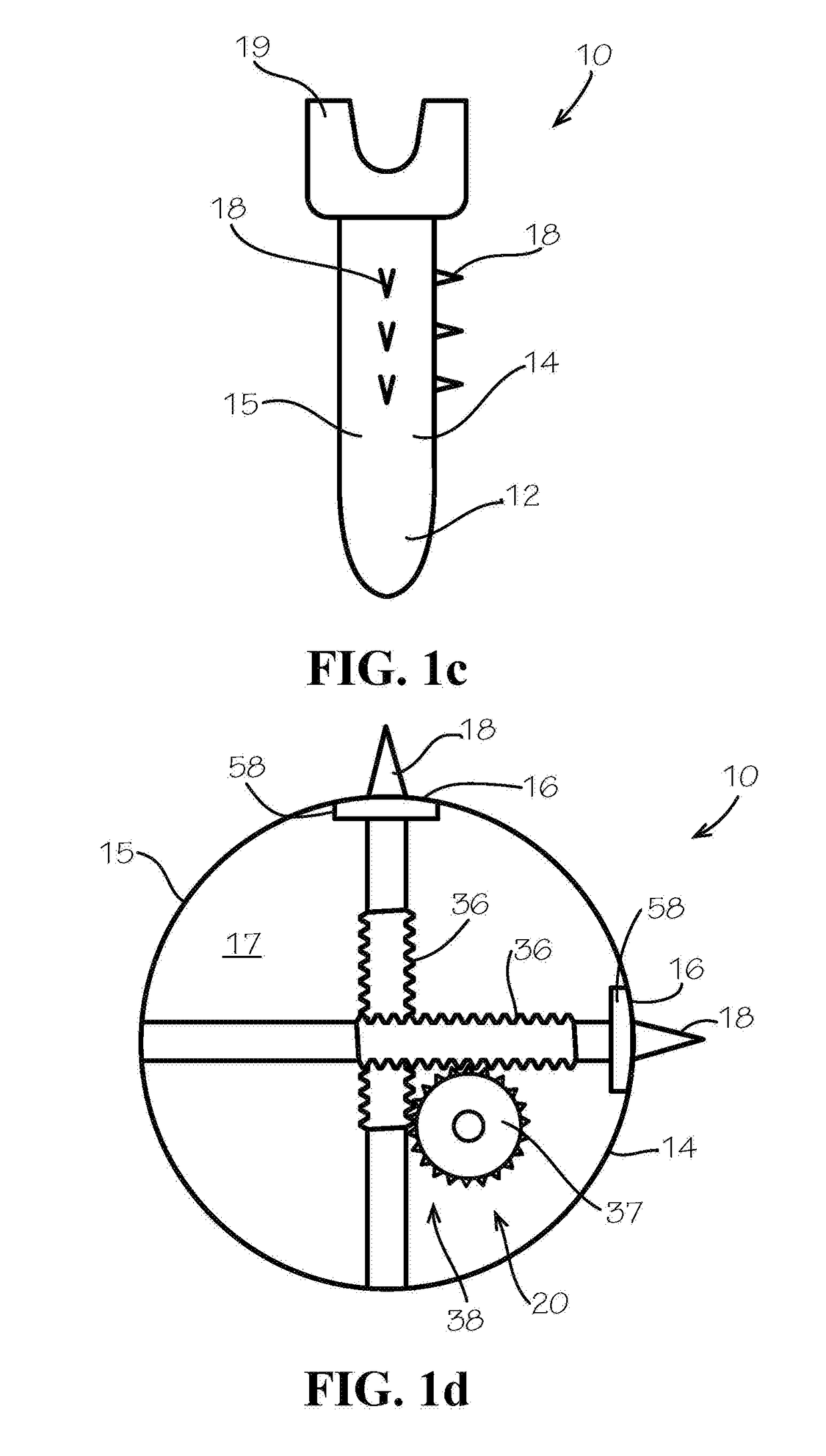
A bone fixation screw device for implantation into a bone of a patient is disclosed. The screw device includes a screw body having an outer surface. A plurality of outer screw threads extends around the outer surface of the screw body. A plurality of apertures or passages is defined through the outer surface. A plurality of anchors can extend out of corresponding apertures in the screw body. The anchors can be inserted into a patient's bone to further fixate and purchase the bone screw within the patient's bone. The screw body can include an inner cavity, the plurality of apertures each being open to the inner cavity. The anchors can extend out of corresponding apertures from the inner cavity.

Description

CROSS-REFERENCES TO RELATED APPLICATIONS[0001]This application is a non-provisional of U.S. Patent Application Ser. No. 62 / 418,533 filed Nov. 7, 2016 entitled TRANSCORTICAL FIXATION PEDICLE SCREW WITH DEPLOYABLE ANCHORS, which is herein incorporated by reference in its entirety.[0002]A portion of the disclosure of this patent document contains material that is subject to copyright protection. The copyright owner has no objection to the reproduction of the patent document or the patent disclosure, as it appears in the U.S. Patent and Trademark Office patent file or records, but otherwise reserves all copyright rights whatsoever.STATEMENT REGARDING FEDERALLY SPONSORED RESEARCH OR DEVELOPMENT[0003]Not ApplicableREFERENCE TO SEQUENCE LISTING OR COMPUTER PROGRAM LISTING APPENDIX[0004]Not ApplicableBACKGROUND OF THE INVENTION[0005]The present invention relates generally to bone fixation devices, and more particularly, to improved bone screw constructs.[0006]The prevalence of degenerative ...

Claims


Application Information

Patent Timeline
Patent Type & Authority Applications(United States)
IPC IPC(8): A61B17/86A61B17/84
CPCA61B17/864A61B17/8605A61B17/846A61B2017/0412A61B17/8685A61B17/683A61B90/92A61B17/7074A61B17/863A61B2017/8655A61B17/7032A61B17/7076A61B2017/00539A61B2017/00544
Inventor MCGIRT, MATTHEW J.
Owner MIRUS LLC
Learn More