Reaction tube structure and substrate processing apparatus

a substrate processing and reaction tube technology, applied in the direction of coatings, chemical vapor deposition coatings, metallic material coating processes, etc., can solve the problems of slow gas flow velocity of the gas on the surface of each plurality of stacked wafers from the upper end to the lower end of the boat, and achieve the effect of increasing the gas flow velocity

Active Publication Date: 2018-05-24
KOKUSA ELECTRIC CO LTD
View PDF8 Cites 315 Cited by
  • Summary
  • Abstract
  • Description
  • Claims
  • Application Information

AI Technical Summary

Benefits of technology

[0006]Described herein is a technique capable of increasing a flow velocity of gas at a surface of a wafer.

Problems solved by technology

However, the flow velocity of the gas on the surface of each of plurality of stacked wafers from the upper end to the lower end of the boat is slow.
Since outgas of gas (outgas) generated on the wafer surface during heat treatment becomes insufficient, out gas increases.

Method used


Image

  • Reaction tube structure and substrate processing apparatus
  • Reaction tube structure and substrate processing apparatus
  • Reaction tube structure and substrate processing apparatus

Examples


first embodiment

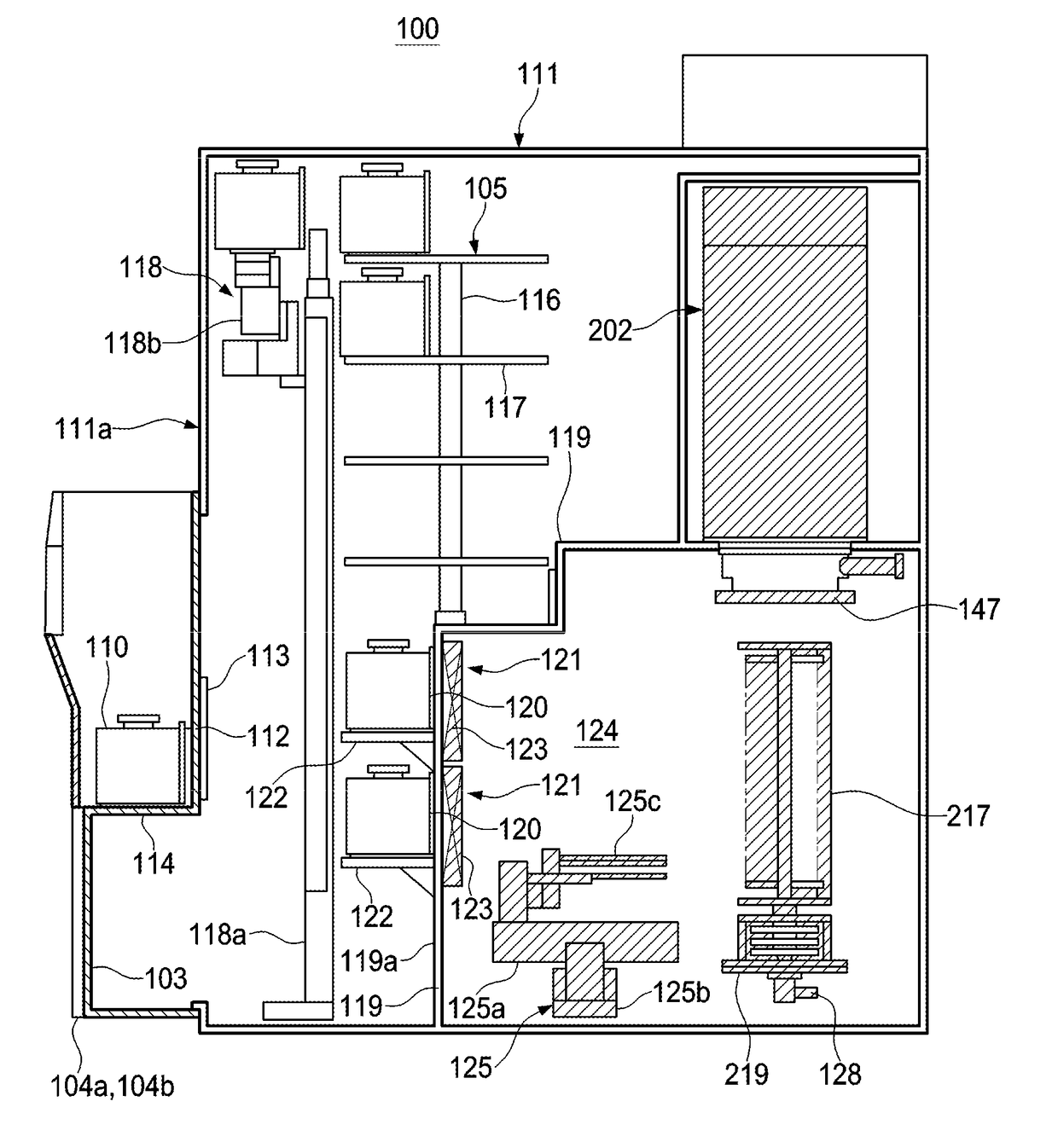
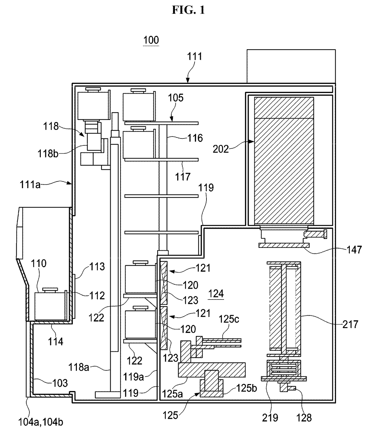
[0045]The first embodiment will be described in more detail with reference to FIGS. 3 through 6, FIG. 9 and FIG. 10.

[0046]As shown in FIG. 3, the processing furnace 202 includes a heater (heating mechanism) 206. The heater 206 is cylindrical and vertically supported by a support plate (heater base) 251.

[0047]A liner tube (outer tube) 205 is provided inside the heater 206 concentrically with the heater 206. The liner tube 205 is made of a heat-resistant material such as SiC, and is cylindrical with a closed upper end and an open lower end. A reaction tube (inner tube) 204 is concentrically provided inside the liner tube 205. The reaction tube 204 is made of a heat-resistant material such as quartz, and is cylindrical with a closed upper end, and an open lower end. The hollow center portion of the reaction tube 204 functions as process chamber 201. The boat 217 supporting the wafers 200 in horizontal orientation vertically aligned in multiple stages is accommodated in the process cham...

second embodiment

[0080]The second embodiment is described with reference to FIGS. 7 and 8.

[0081]The second embodiment shown in FIGS. 7 and 8 differs from the first embodiment shown in FIGS. 4 and 5 in that a second buffer unit (buffer box) 234 is provided at the gas outlet 231. Therefore, only the second buffer unit 234 will be described in detail, and the descriptions of the components the same as those of the first embodiment will be omitted.

[0082]First, the reaction tube structure 2040 of the first embodiment shown in FIG. 4 and a reaction tube structure 2040′ of the second embodiment shown in FIG. 7 are compared. In the reaction tube structure 2040′ according to the second embodiment, the first buffer unit 232 and the plurality of gas supply holes 232a are the same as those of the first embodiment. The reaction tube structure 2040′ according to the second embodiment further includes the second buffer unit 234 connected to the gas outlet 231. The second buffer unit 234 is provided in the process ...


PUM

PropertyMeasurementUnit
temperatureaaaaaaaaaa
diameteraaaaaaaaaa
diameteraaaaaaaaaa

Abstract

A substrate processing apparatus includes a reaction tube defining a substrate processing chamber; a gas inlet provided at a lower portion of the reaction tube to supply a process gas; a first buffer unit for temporarily retaining the process gas, the first buffer unit at a first side of an inner surface of the reaction tube and includes a plurality of gas supply holes; and a gas outlet provided at a second side of the inner surface of the reaction tube opposite to the first side, to exhaust the process gas from the process chamber. The gas supply holes are provided from an upper end portion of the first buffer unit to a lower end portion of the first buffer unit, and the process gas is supplied through the plurality of gas supply holes into the process chamber, passes through the process chamber, and exhausted through the gas outlet.

Description

CROSS-REFERENCE TO RELATED PATENT APPLICATION[0001]This non-provisional U.S. patent application claims priority under 35 U.S.C. §119 of Japanese Patent Application No. 2016-224973, filed on Nov. 18, 2016 and Japanese Patent Application No. 2017-201009, filed on Oct. 17, 2017, the entire contents of which are hereby incorporated by reference.BACKGROUND1. Field[0002]The present disclosure relates to a reaction tube structure and a substrate processing apparatus including the same.2. Description of the Related Art[0003]Conventional substrate processing apparatus subjects a substrate to processes such as oxidation and diffusion (particularly, pyroprocessing, dry oxidation and annealing). For example, in the conventional substrate processing apparatus, a gas is introduced through a gas inlet installed at the bottom of a reaction tube, and then supplied into the reaction chamber through the ceiling portion of the reaction tube. The gas supplied in the reaction chamber flows from the upper...

Claims


Application Information

Patent Timeline
Patent Type & Authority Applications(United States)
IPC IPC(8): C23C16/455C23C16/52C23C16/44C23C16/458H01L21/673
CPCC23C16/45578C23C16/52C23C16/4412C23C16/458H01L21/67309H01L21/31H01L21/67017H01L21/67109H01L21/67757H01L21/67769C23C16/45502C23C16/4584H01L21/67098H01L21/67772H01L21/67739
Inventor MARUBAYASHI, TETSUYAMURATA, SATORUTAKAGI, KOSUKEHIRANO, ATSUSHIYAMADA, KIYOAKIMORIKAWA, HARUO
Owner KOKUSA ELECTRIC CO LTD
Why Eureka
Try Eureka