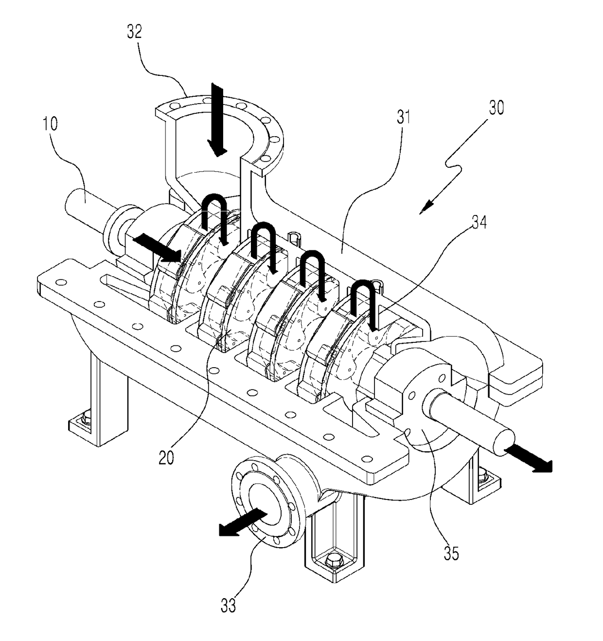
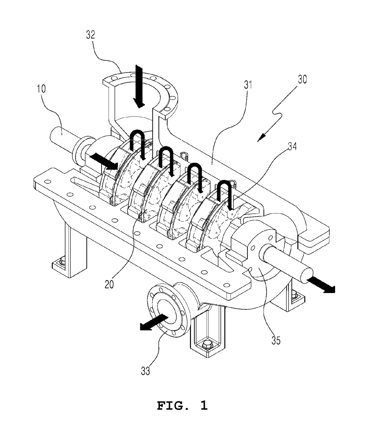
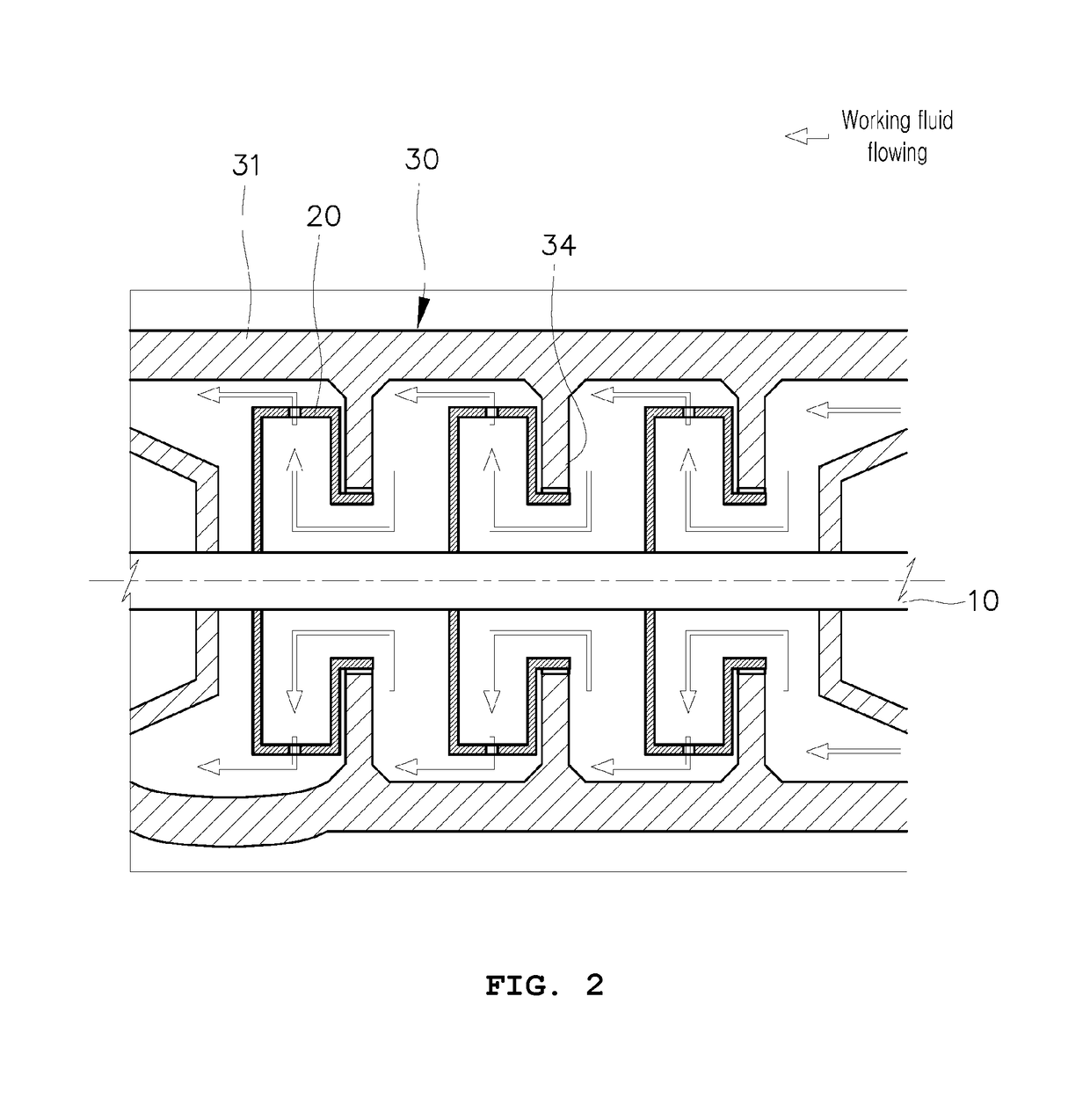
Reaction-type steam turbine

a steam turbine and reaction-type technology, applied in the direction of machines/engines, stators, non-positive displacement engines, etc., can solve the problems of large pressure difference between the inside and the outside of the nozzle-equipped rotary body, performance degradation and life span reduction, and increase operation costs, so as to reduce friction loss and prolong the life of the bearing element.

Inactive Publication Date: 2018-05-24
POSCO ENERGY CO LTD
View PDF3 Cites 1 Cited by
  • Summary
  • Abstract
  • Description
  • Claims
  • Application Information

AI Technical Summary

Benefits of technology

[0025]According to the present invention, the steam turbine includes a guide panel at each rear end of a plurality of nozzle-equipped rotary bodies composed of multiple stages to minimize the friction loss that may be generated when the ejected working fluid comes into contact with the nozzle-equipped rotary body, thereby vibration / fatigue problems caused by stress generation can be minimized by reducing the load in the axial directional with regards to the turbine shaft and the life span of bearing elements can be extended.

Problems solved by technology

On the other hand, the nozzle-equipped rotary body optimized to meet these conditions results in a large pressure difference between the inside and the outside of the nozzle-equipped rotary body, and the strong axial force in a single direction to the turbine shaft is generated due to the pressure difference.
Such an occurred axial force may increase the mechanical load of the bearings, which may cause performance degradation and life span reduction, and cause the operation costs to increase due to the deterioration of the turbine performance and frequent maintenance.

Method used


Image

  • Reaction-type steam turbine
  • Reaction-type steam turbine
  • Reaction-type steam turbine

Examples


Embodiment Construction

[0039]The specific structure or functional description presented in the embodiments of the present invention is merely illustrative for the purpose of describing an embodiment according to the concept of the present invention, and embodiments according to the concept of the present invention may be embodied in various forms. And the present invention should not be construed as limited to the embodiments set forth herein, but should be understood to include all modifications, equivalents, and alternatives falling within the spirit and scope of the invention.

[0040]On the other hand, in the present invention, the terms first and / or second etc. may be used to describe various components, but the components are not limited to the terms. For example, the term, a first component may be referred to as a second component since the terms are defined only for the purpose of distinguishing one component from another component to the extent not departing from the scope of the invention in accord...


PUM


Abstract

Embodiments of the present invention relate to a steam turbine in which unnecessary axial force is reduced. The steam turbine is capable of preventing a working fluid discharged from each nozzle-equipped rotary body from acting as resistance to the nozzle-equipped rotary bodies. The steam turbine includes a housing, a turbine shaft supported pivotably in the housing, a nozzle-equipped rotary body, and a guide panel. The nozzle-equipped rotary body is in the shape of a plurality of disks stacked along the axial direction of the turbine shaft, is integrally coupled to the turbine shaft, and has at least one or more nozzle holes formed therein so as to rotate as the working fluid is ejected. The guide panel is positioned at the rear end in a flow direction of the working fluid of the nozzle-equipped rotary body and fixed to the housing to guide the flow of the working fluid.

Description

CROSS-REFERENCE TO RELATED PATENT APPLICATIONS[0001]This patent application is a continuation of PCT / KR2016 / 005227, filed May 18, 2016, which claims priority to Korean Application No. 10-2015-0098508, filed Jul. 10, 2015, the entire teachings and disclosure of which are incorporated herein by reference thereto.FIELD OF THE INVENTION[0002]The present invention relates to a steam turbine, in particular to a steam turbine reducing unnecessary axial force, which can affect a turbine shaft transmitting the rotational driving force of a plurality of nozzle-equipped rotary bodies connected in multiple stages, and capable of preventing an working fluid discharged from each nozzle-equipped rotary body from acting as resistance to the nozzle-equipped rotary bodies.BACKGROUND OF THE INVENTION[0003]A reaction-type steam turbine obtains the rotational energy by reaction of the discharged steam energy, so that high heat efficiency can be obtained with a simple structure. Accordingly, it is suitab...

Claims


Application Information

Patent Timeline
Patent Type & Authority Applications(United States)
IPC IPC(8): F01D1/32F01D1/34F01D9/02
CPCF01D1/32F01D1/34F01D9/02F05D2220/31F01D1/026F01D1/14F01D1/22
Inventor LEE, SANGHOONLEE, JEAJUNLIM, JU CHANGLEE, SANG MYEONGOH, SUNGKEUN
Owner POSCO ENERGY CO LTD
Why Eureka
Try Eureka