Centrifugal engine

a centrifugal engine and centrifugal technology, applied in the field of centrifugal engines, can solve problems such as limiting the maximum theoretical efficiency, and achieve the effects of less turbulence, less acoustic emissions, and reduced friction losses

Inactive Publication Date: 2007-01-18
HAUCK THOMAS +1
View PDF7 Cites 1 Cited by
  • Summary
  • Abstract
  • Description
  • Claims
  • Application Information

AI Technical Summary

Benefits of technology

[0014] The Centrifugal Engine causes less turbulence and less acoustic emissions making it advantageous in scientific or military applications for submarines. The friction losses are minimized compared to conventional fluid-flow systems since the work fluid does not pass through the engine but is merely accelerated by a low pressure field. Therefore the Centrifugal Engine operates more efficiently than currently known solutions in marine propulsion.

Problems solved by technology

The friction losses caused by this throughput of the fluid through the engine limit the maximum theoretical efficiency.

Method used


Image

  • Centrifugal engine
  • Centrifugal engine
  • Centrifugal engine

Examples


Embodiment Construction

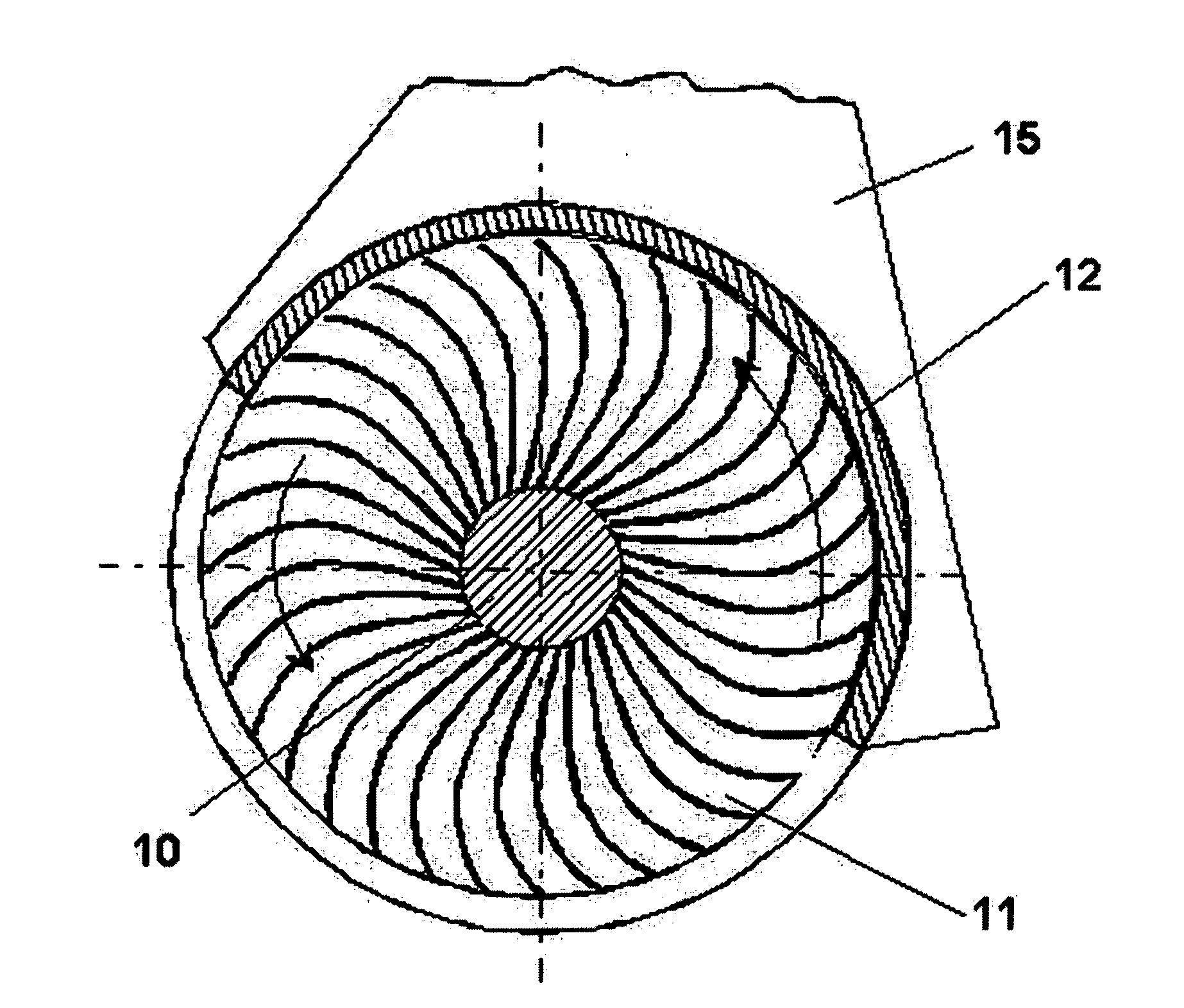
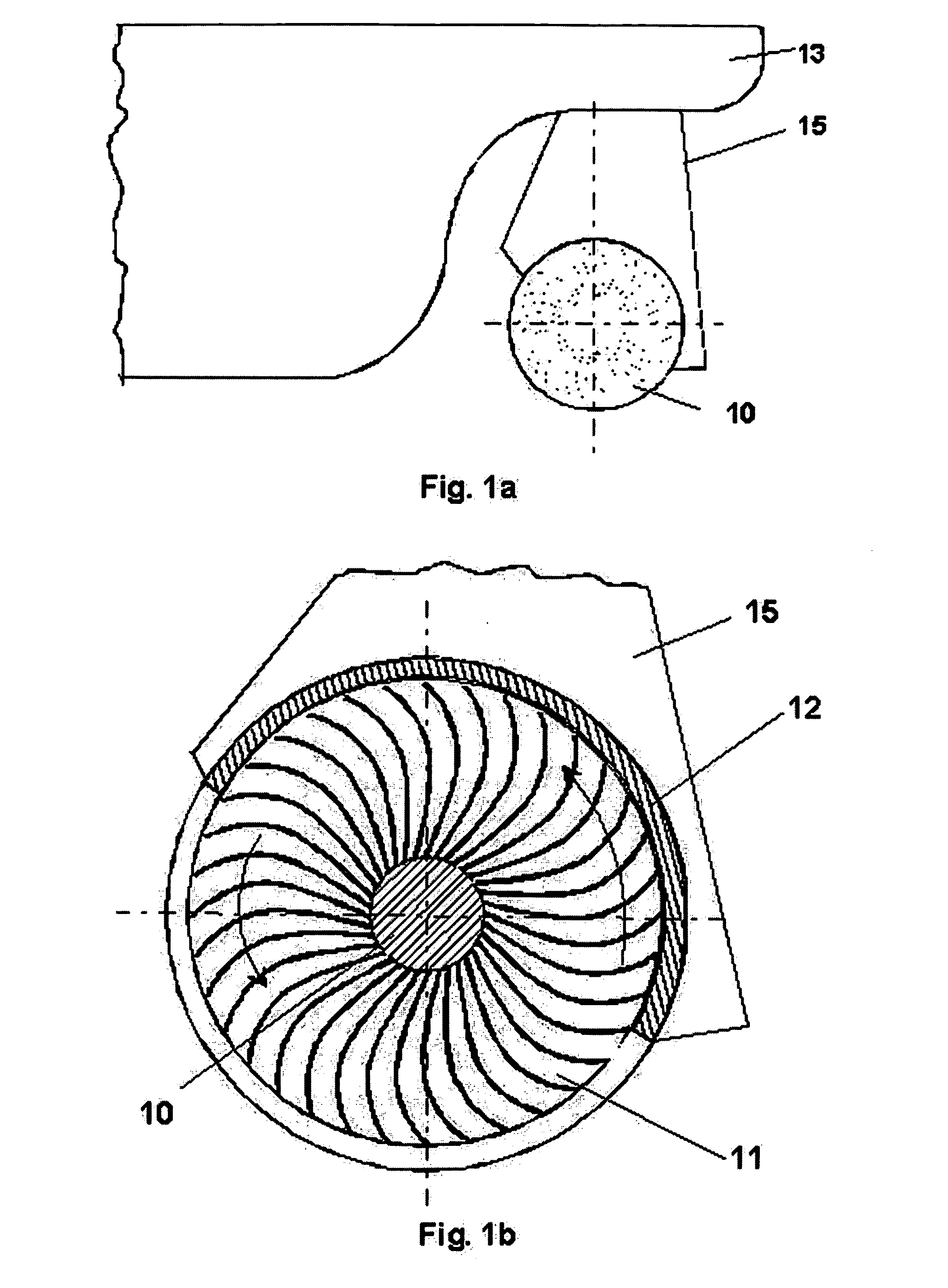
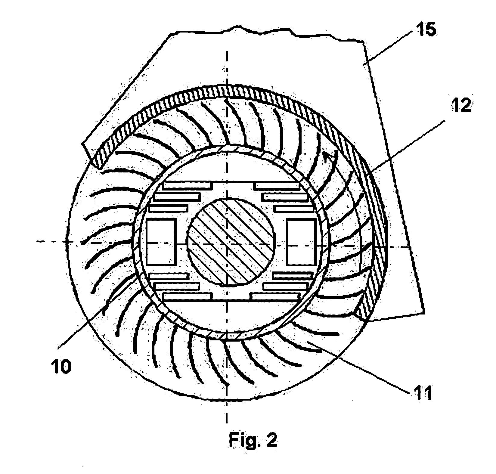
[0032]FIG. 1a shows a side view of the Centrifugal Engine mounted to the rear of a vessel. Referring additionally to FIG. 1b, an apparatus in accordance with the invention comprises a rotor shaft, a rotor 10, and a cylindrical rotor enclosure 12. The rotor is mounted to the rotor shaft and consists of a hub with radially mounted blades 11. The rotor 10 is enclosed by a cylindrical enclosure 12 in such a manner that the rotor 10 can freely spin in the enclosure 12. The rotor blades 11 form cells with the surrounding enclosure. The enclosure 12 is constructed in such a way that the rotor exposes some cells to the working fluid. The top and bottom of the rotor 10 as well as a portion of the side walls is covered by the cylindrical enclosure 12. The clearances between the rotor blades and the enclosure are kept as small as technical possible to avoid work fluid being transported through the engine. The rotor shaft that is mounted to the rotor in a fixed manner passes through the enclosu...


PUM


Abstract

A novel kind of propulsion system that uses centrifugal force to accelerate the surrounding work-fluid. A rotor (10) with radially mounted blades (11) is enclosed by a cylindrical enclosure (12). The cylinder wall of the enclosure (12) is partially open to the surrounding work fluid. The rotor is rotated in the housing and surrounding fluid thereby generating the propulsive force.

Description

CROSS-REFERENCE TO RELATED APPLICATIONS [0001] This application claims the benefit of German Patent Application Number 102005005142.1 entitled “Zentrifugalarbeitsmaschine”, filed Feb. 02, 2005, in Germany by the present inventors. The above priority application is hereby incorporated herein by reference. BACKGROUND OF THE INVENTION Field of Invention [0002] This invention relates to marine and aeronautic propulsion systems, specifically a propulsion system that can replace a conventional propeller. [0003] All known marine and aeronautic propulsion systems share the common working principle in that the work fluid flows through the engine. This is true for propellers, jets, turbines, and water wheels. EP-1355822 describes a water wheel with sprockets that move the work fluid through an enclosure using a rotor. The sprockets move the surrounding water into a canal within the engine. This water stream gets accelerated in the engine and expelled to generate the propulsion. These are in s...

Claims


Application Information

Patent Timeline
Patent Type & Authority Applications(United States)
IPC IPC(8): F01D5/30
CPCB63H1/04F04D23/00F04D5/00
Inventor HAUCK, THOMASHAUCK, GEORG
Owner HAUCK THOMAS
Why Eureka
Try Eureka