Compressor

a compressor and compressor technology, applied in the field of compressors, can solve the problems of high relative speed, serious vibration and noise problems, friction loss, etc., and achieve the effects of reducing the length of the rotary shaft, minimizing the height of the compressor, and reducing the siz

Active Publication Date: 2011-06-02
LG ELECTRONICS INC
View PDF36 Cites 2 Cited by
  • Summary
  • Abstract
  • Description
  • Claims
  • Application Information

AI Technical Summary

Benefits of technology

[0037]The thus-constructed compressor according to the present invention can enables a compact design because a compression space within the compressor is formed by a rotor of an electric motor part driving the compressor by installing a compression mechanism part and the electric motor part in a radius direction, thus minimizing the height of the compressor and reducing the size.
[0038]Additionally, the compressor according to the present invention is structurally stabilized since the length of a rotary shaft can be reduced, and, hence, advantageous in terms of vibration design and can increase operational reliability.
[0039]Additionally, the compressor according to the present invention can significantly decrease a difference in relative speed between the first rotary member and the second rotary member and hence minimize a resulting friction loss because a refrigerant is compressed in the compression space between the first and second rotary members as the first rotary member rotates along with the second rotary member by transmitting a rotational force to the second rotary member, thus maximizing the efficiency of the compressor.
[0040]Furthermore, since the vane partitions the compression space while reciprocating between the first rotary member and the second rotary member without being in sliding contact with first rotary member or second rotary member, the leakage of the refrigerant in the compression space can be minimized by means of a simple structure, thereby maximizing the efficiency of the compressor.
[0041]Moreover, the first bearing and the second bearing include journal bearings being in contact with the inner peripheral surface of the first rotary shaft and the outer peripheral surface of the second rotary shaft, and for rotatably supporting them and thrust bearings being in contact with surfaces contacting the second rotary member and the covers in a load direction, and for rotatably supporting them, whereby the rotation of the rotary members can be firmly supported.

Problems solved by technology

While the reciprocating compressor has superior mechanical efficiency, such a reciprocating motion causes serious vibration and noise problems.
Between the components which are thus in sliding contact, a high relative speed exists, and hence a friction loss occurs.
This leads to a degradation of the efficiency of the compressor.
Further, there is always the possibility of refrigerant leakage on a contact surface between the vane and the roller which are in sliding contact, thus reducing mechanical reliability.
Therefore, this patent still has the problem of the conventional rotary compressor.
That is to say, the rotary compressor according to this publication is problematic in that the height of the compressor is inevitably large because a separate electric motor part has to be laminated in a height direction relative to a compression mechanism part including a rotor, a cylinder, and a vane, thereby making a compact design difficult.

Method used


Image

  • Compressor
  • Compressor
  • Compressor

Examples


first embodiment

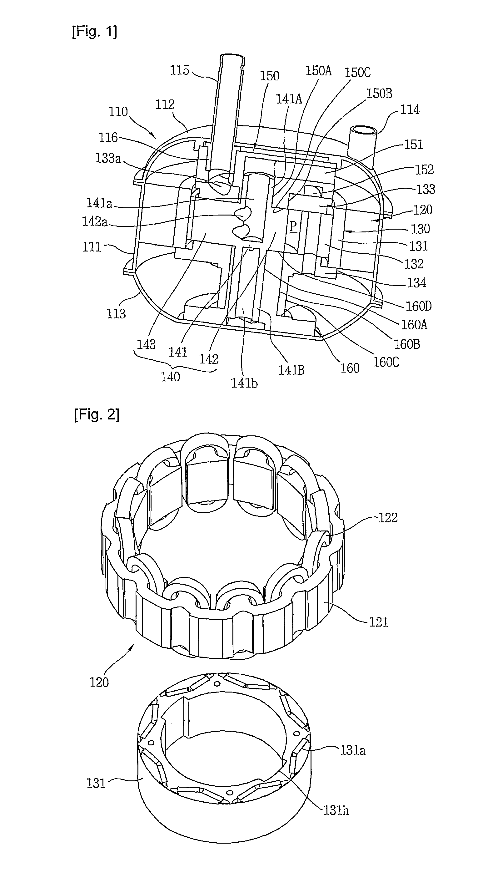
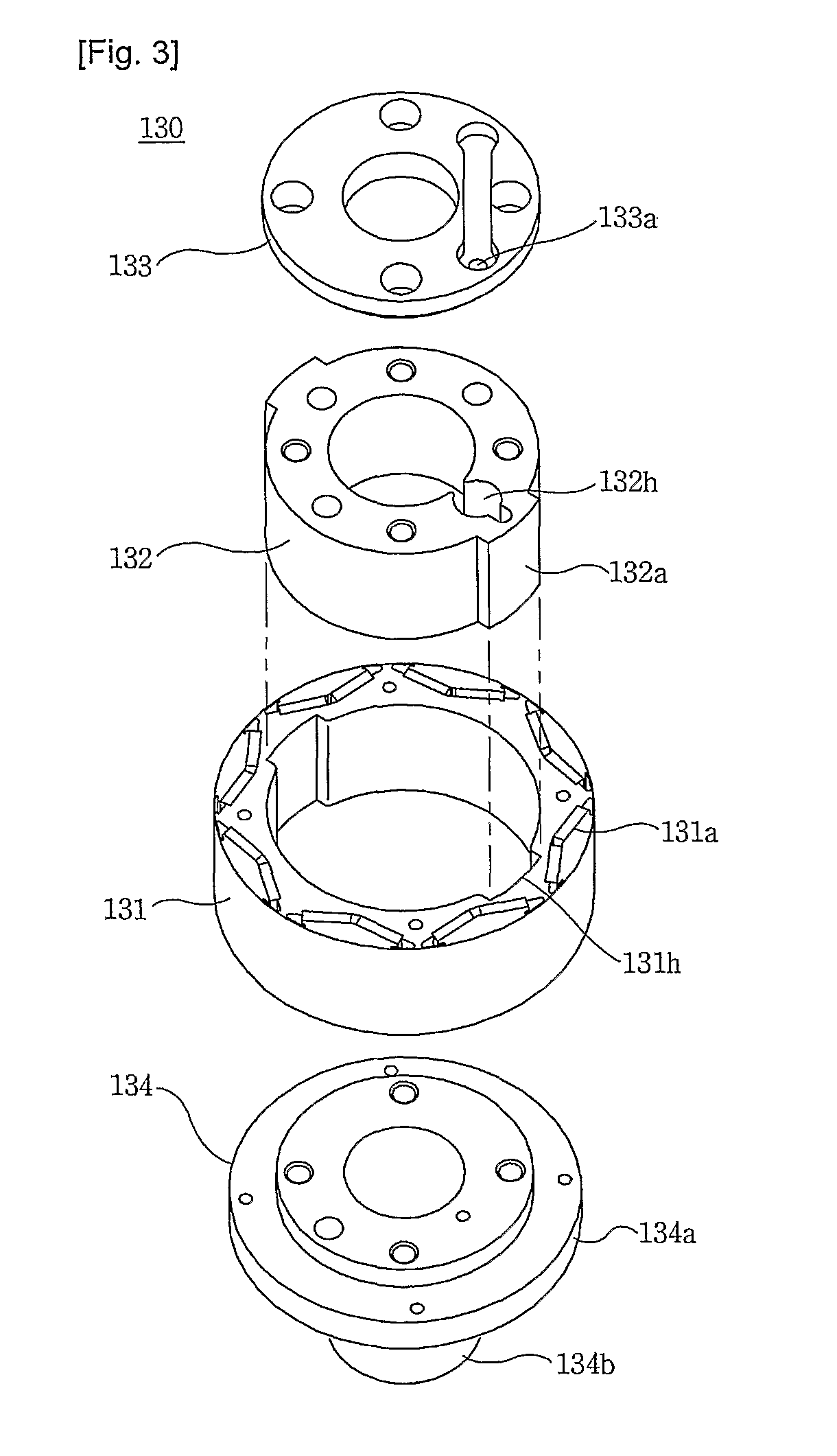
[0058]the compressor according to the present invention comprises, as shown in FIG. 1, a hermetically sealed container 110, a stator 120 installed inside the hermetically sealed container 110, a first rotary member 130 rotatably installed inside the stator 120 by a rotational electromagnetic field from the stator 120, a second rotary member 140 for compressing a refrigerant between the first and second rotary members 130 and 140 while rotating inside the first rotary member 130 upon receipt of a rotational force from the first rotary member 130, and first and second bearings 150 and 160 for rotatably supporting the first rotary member 130 and the second rotary member 140 on the inside of the hermetically sealed container 110. An electric motor part for providing electric power by an electrical action employs a kind of BLDC motor including a stator 120 and a first rotary member 130, and a compression mechanism part for compressing the refrigerant by a mechanical action includes a fir...

second embodiment

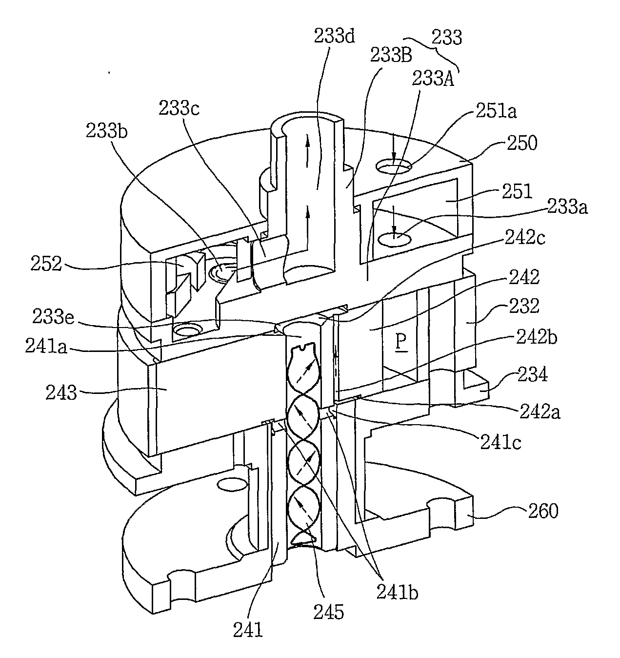
[0090]The hermetically sealed container 210 comprises a cylindrical body portion 211 and upper / lower shells 212 and 213 coupled to upper and lower parts of the body portion 211, and stores oil for lubricating the first and second rotary members 230 and 240 (shown in FIG. 1) up to an appropriate height. A suction pipe 214 for sucking a refrigerant is provided at one side of the upper shell 213, and a discharge pipe 215 for discharging the refrigerant is provided at the center of the upper shell 213. The type of the compressor is determined as a high pressure type or a low pressure type according to a connection structure of the suction pipe 214 and the discharge pipe 215. In the present invention, the compressor is configured as the low pressure type. To this end, the suction pipe 214 is connected to the hermetically sealed container 210, and at the same time the discharge pipe 215 is directly connected to the compression mechanism part. Thus, when a low pressure refrigerant is sucke...


PUM


Abstract

A compressor comprises: a hermetically sealed container; a stator fixedly installed within the hermetically sealed container; a first rotary member rotating, within the stator, around a first rotary shaft longitudinally extending concentrically with the center of the stator by a rotating electromagnetic field from the stator, and provided with first and second covers fixed to upper and lower parts and rotating integrally with each other; a second rotary member space for compressing a refrigerant in a compression space formed between the first and second rotary members while rotating, within the first rotary member, around the second rotary shaft extending through the first and second covers upon receipt of a rotational force from the first rotary member; a vane for transmitting the rotational force to the second rotary member from the first rotary member, and partitioning the compression space into a suction region for sucking the refrigerant and a compression region for compressing/discharging the refrigerant; and first and second bearings fixed to the inside of the hermetically sealed container, and rotatably supporting the first and second rotary members in an axial direction.

Description

TECHNICAL FIELD[0001]The present invention relates to a compressor, and more particularly, to a compressor which enables a compact design by forming a compression space within the compressor by a rotor of an electric motor part driving the compressor, maximizes compression efficiency by minimizing friction loss between rotating elements within the compressor, and has a structure capable of minimizing leakage of refrigerant within the compression space.BACKGROUND ART[0002]In general, a compressor is a mechanical apparatus for compressing the air, refrigerant or other various operation gases and raising a pressure thereof, by receiving power from a power generation apparatus such as an electric motor or turbine. The compressor has been widely used for an electric home appliance such as a refrigerator and an air conditioner, or in the whole industry.[0003]The compressors are roughly classified into a reciprocating compressor in which a compression space for sucking or discharging an op...

Claims


Application Information

Patent Timeline
Patent Type & Authority Applications(United States)
IPC IPC(8): F04B35/04
CPCF04C18/322F04C29/0085F04C23/008
Inventor LEE, KANGWOOKSHIN, JIN-UNGKWON, YONGCHOLLEE, GEUN-HYOUNG
Owner LG ELECTRONICS INC
Why Eureka
Try Eureka