Device and method for perforating a dense bone layer

Pending Publication Date: 2021-06-17
BOSONIC AG
View PDF0 Cites 0 Cited by
  • Summary
  • Abstract
  • Description
  • Claims
  • Application Information

AI Technical Summary

Benefits of technology

The present invention is a device and method for creating accurately defined openings in dense bone without leaving a significant amount of bone tissue unaffected. The device includes a perforator that can be vibrated in impaction direction and / or urged against the bone layer to create the opening. The perforator has a distal face that is positioned and held against the bone layer and impacted into it. The perforator creates an opening that is at least partially cylindrical and has uncompromised bone tissue at the bottom and / or inside the opening. The device can also include a cannula or guide shaft to transmit vibrational energy and minimize friction between the device and the cannula. The invention allows for better predictability and optimization regarding flow through the perforation and mechanical weakening of the bone layer.

Problems solved by technology

The advantage of the microdrilling process is the fact that debris are easily removed from the bore along the grooves of the drill bit and therefore do not obstruct blood flow through the produced bore; its disadvantage is the inevitable thermal load on the bone tissue and the possibly non-negligible mechanical weakening of the dense bone plate.
The advantages of the microfracturing process are its simplicity, the possibly smaller opening depth, and the fact that substantially no debris remains in the opening leaving the latter unobstructed; its disadvantages are the compaction of the bone tissue adjoining the opening (damage to and sealing of trabecular bone structure), the friction between the bone tissue and the tool, and in particular the dependence of the achievable microfracturing on the usually not very well known quality of the bone tissue at hand, which renders the perforation quality and the mechanical weakening of the dense bone plate hardly predictable.

Method used


Image

  • Device and method for perforating a dense bone layer
  • Device and method for perforating a dense bone layer
  • Device and method for perforating a dense bone layer

Examples


Embodiment Construction

lass="d_n">[0050]In all appended Figs., same reference numerals designate same elements or similar elements serving same functions.

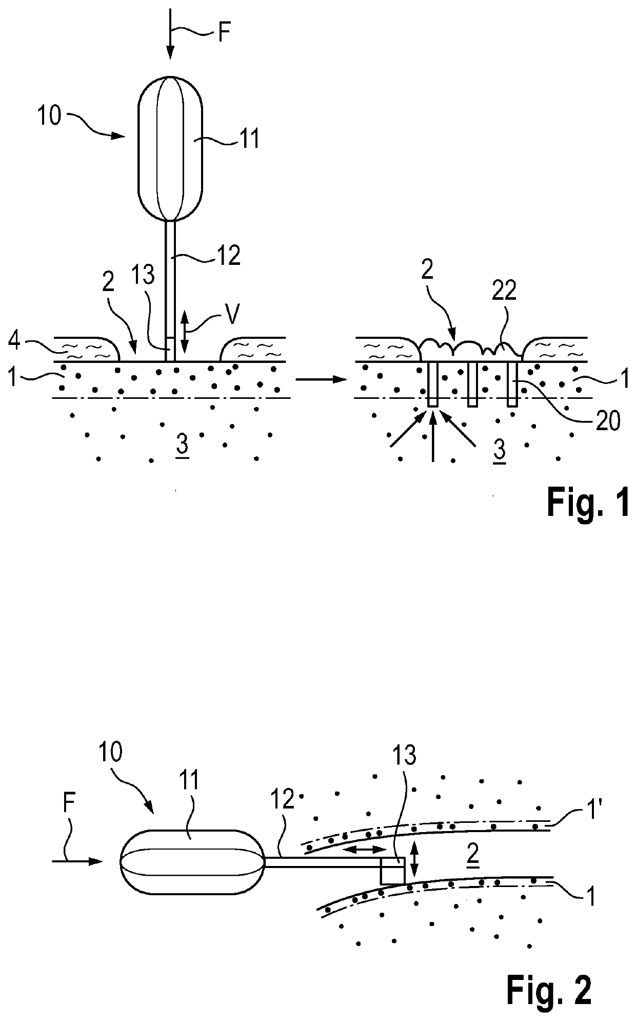
[0051]FIG. 1 illustrates in a very schematic manner, the direct approach for perforating a dense bone layer 1 using a device 10 according to the invention, wherein the left hand side of FIG. 1 shows the device 10 positioned for the perforation process, and the right hand side shows the perforated dense bone layer and illustrates the desired flow of blood, oxygen and / or cells through the perforation. As already mentioned further above, the dense bone layer is situated between a repair site 2 (outer side of the dense bone layer) and a region 3 or layer of trabecular bone and / or bone marrow (inner side of bone layer), wherein there is usually a gradual transition between dense and trabecular bone tissue and not, as illustrated, a sharp line separating the two. The dense bone layer 1 is, e.g., a subchondral bone plate and the repair site 2 is a location, in ...


PUM


Abstract

A device and method for perforating a dense bone layer. The device includes a vibration generator for generating mechanical vibration, in particular ultrasonic vibration, and an instrument with an elongated shaft and a distal end piece including a perforator. The distal end piece is arranged at a distal end of the shaft and the proximal end of the shaft is connected or connectable to the vibration generator. The perforator has the form of a solid or a hollow cylinder. The vibration generator, the shaft and the distal end piece are adapted to each other for the shaft to transmit, when connected to the activated vibration generator, mechanical vibration from the vibration generator to the distal end piece and for vibrating the perforator in a direction parallel to its cylinder axis.

Description

BACKGROUND OF THE INVENTIONField of the Invention[0001]The invention resides in the field of medical technology and regards a device suitable for perforating a dense bone layer with the aim of enabling transport of blood, oxygen and / or viable cells through the dense bone layer from trabecular bone tissue and / or bone marrow on an inner side of the dense bone layer to a repair site on an opposite, outer side of the dense bone layer, and for therewith enhancing tissue repair or tissue regeneration and tissue growth in the repair site. The invention also relates to a method for perforating a dense bone layer with the aid of the named device.Description of Related Art[0002]Methods in the field of the invention are known as marrow-stimulation and include microdrilling or microfracturing the dense bone layer situated between vascularized trabecular bone and / or bone marrow (inner side of the dense bone layer) and a tissue layer in need of tissue repair, tissue regeneration or tissue growth ...

Claims


Application Information

Patent Timeline
IPC IPC(8): A61B17/16A61B17/34A61B17/32A61B17/3205
CPCA61B17/1637A61B17/1604A61B17/3421A61B17/32002A61B2090/036A61B2017/320064A61B2017/32007A61B2017/320072A61B17/32053A61B17/320068A61B2017/320098A61B17/1635A61B17/3472A61B17/1671A61B2017/3454A61D1/00
Inventor SCHWERY, ANDRÈMAYER, JÖRG
Owner BOSONIC AG
Why Eureka
Try Eureka