System and method for parallel power monitoring

a technology of parallel power monitoring and monitoring system, applied in the field of parallel power monitoring system and method, can solve the problems of increasing setup times, reducing the size of the battery, and small development team only having enough resources to obtain one or two daqs, so as to achieve high accuracy and cost efficiency. the effect of cost saving

Inactive Publication Date: 2018-05-24
GOOGLE LLC
View PDF0 Cites 2 Cited by
  • Summary
  • Abstract
  • Description
  • Claims
  • Application Information

AI Technical Summary

Benefits of technology

[0005]The technology relates to a system and method for monitoring, in parallel, the power consumption of multiple subsystems of a device under test (“DUT”). Aspects of the technology provide highly accurate and affordable power sampling tools for monitoring the power consumption of a DUT. For instance, some embodiments provide one or more of the following: (1) the system is capable of monitoring, in parallel, the power consumption of numerous subsystems of a DUT, (2) the system is extremely cost efficient, (3) the timing resolution of the power consumption data collected by the system is finer than 1 ms, and (4) the timing accuracy of the power consumption data collected by the system is within 10 ns.

Problems solved by technology

However, as devices get smaller, the size of the battery also must shrink.
However, they are often expensive.
As a result, a small development team may only have enough resources to obtain one or two DAQs.
This presents several challenges to the team because the DAQs will need to be shared, which may increase setup times and possibly introduce measurement errors due to human error.
Sequential sampling creates a timing accuracy delta (differential) between the sampling of the first channel and the sampling of the last channel This timing accuracy delta can make it difficult to effectively analyze and correlate the power consumption data from the various sample points.
Therefore, such DAQs are not effective when developing mobile devices that require the timing accuracy to be within, for example, 10 ns, and require the time sampling resolution to be much finer than, for example, 1 ms.

Method used


Image

  • System and method for parallel power monitoring
  • System and method for parallel power monitoring
  • System and method for parallel power monitoring

Examples


Embodiment Construction

[0017]Aspects, features and advantages of the disclosure will be appreciated when considered with reference to the following description of embodiments and accompanying figures. The same reference numbers in different drawings may identify the same or similar elements. Furthermore, the following description is not limiting; the scope of the present technology is defined by the appended claims and equivalents. For example, while certain processes may be shown in the figures as occurring in a linear fashion, this is not a requirement unless expressly stated herein. Different processes may be performed in a different order or concurrently. Steps may also be added or omitted unless otherwise stated.

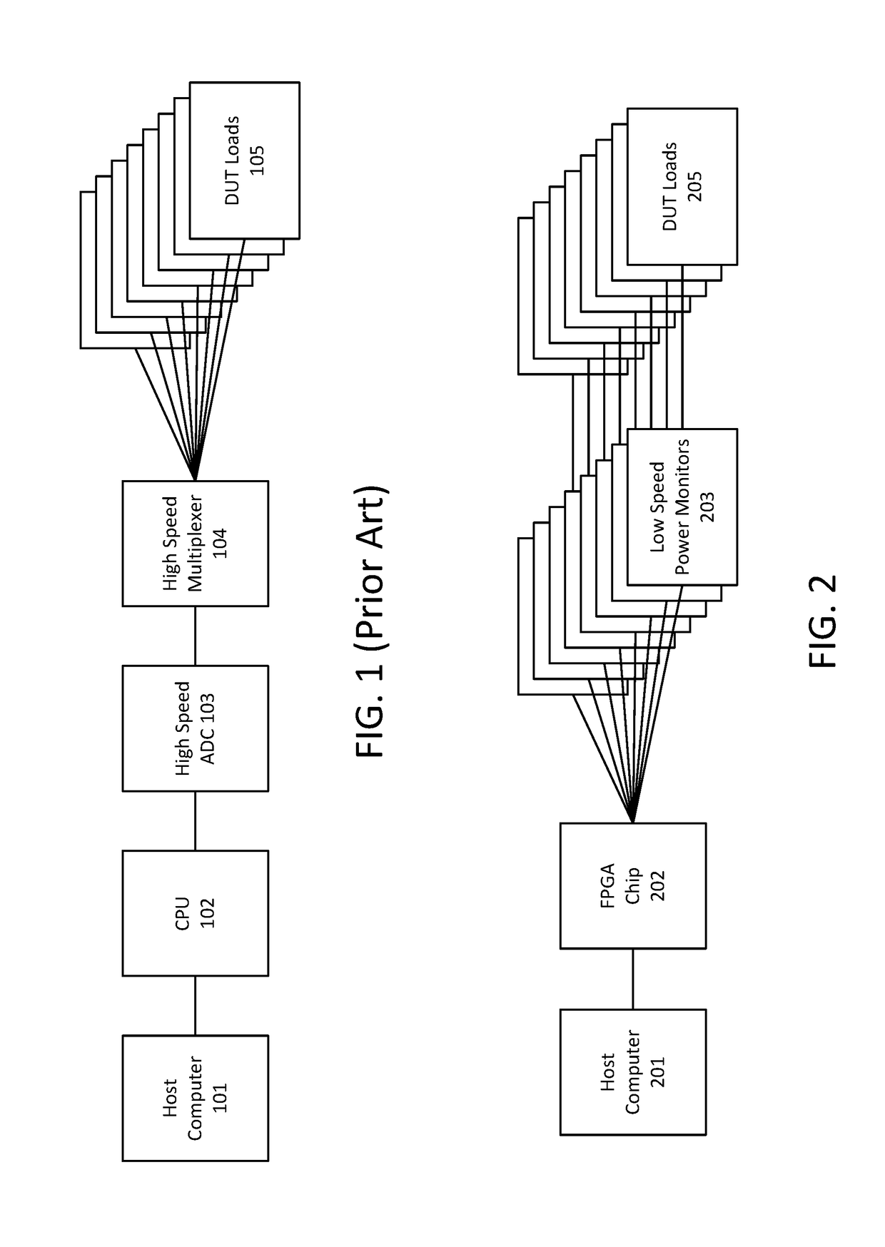
[0018]FIG. 1 illustrates a conventional system for gathering power consumption data for a DUT with multiple subsystems of interest (e.g., DUT loads 105). DAQs may typically contain between one and four high speed analogue-to-digital converters (“ADCs”) and one very high speed multiplexer. As ...


PUM


Abstract

One aspect of the disclosure provides a data acquisition system (“DAQ”) for monitoring, in parallel, the power consumption of a plurality of subsystems of a device under test (“DUT”). The DAQ comprises a plurality of power monitors and a field-programmable gate array (“FPGA”) chip. The power monitors are employed to gather the power consumption for the subsystems of the DUT. The FPGA chip can independently operate the power monitors via internal logic. By employing a parallel array of power monitors, power consumption data can be collected at the same time, and in some cases down to the tens of nanoseconds or less. Once the data is acquired by the FPGA chip, it timestamps, packages and sends the data to a host computer for further processing and/or presentation to a user.

Description

CROSS-REFERENCE TO RELATED APPLICATIONS[0001]The present application claims the benefit of the filing date of U.S. Provisional Patent Application No. 62 / 425,414 filed Nov. 22, 2016, the disclosure of which is hereby incorporated herein by reference.BACKGROUND[0002]As mobile devices become smaller and increasingly complex, it becomes especially important for engineers and developers to be able to accurately and effectively measure the power consumption of the products they are designing. Often, the commercial success of a mobile device is tied to the size of the device and its battery life. However, as devices get smaller, the size of the battery also must shrink. Thus, significant emphasis is often placed on the optimization of power consumption during product development.[0003]Often, in order to successfully and accurately measure the power consumption of a device, a platform system is developed in parallel with the form factor device. This platform system must retain all the funct...

Claims


Application Information

Patent Timeline
Patent Type & Authority Applications(United States)
IPC IPC(8): G01R22/10G01R22/06
CPCG01R22/10G01R22/063G01R21/00G06F5/06G06F13/4068G06F13/4282G06F2213/0016H04Q9/00G06F11/3062G06F11/3013
Inventor LIU, JIANYI
Owner GOOGLE LLC
Why Eureka
Try Eureka