
Phosphorous trifluoride co-gas for carbon implants

a technology of phosphorous trifluoride and carbon implants, which is applied in the direction of phosphorus oxides, phosphorus halides/oxyhalides, lanthanide oxides/hydroxides, etc., can solve the problems of premature failure of ion sources and shorten the life of ion sources

Active Publication Date: 2018-05-24
AXCELIS TECHNOLOGIES
View PDF6 Cites 3 Cited by
  • Summary
  • Abstract
  • Description
  • Claims
  • Application Information

AI Technical Summary

Benefits of technology

The patent describes a process for implanting carbon into a substrate using a mixture of carbon oxide gas and phosphorous trifluoride gas. The process involves ionizing the gas mixture to create a beam of carbon ions and phosphorous oxides, which are then exposed to the substrate to implant the carbon ions. The technical effect of this process is the ability to create a stable and reliable method for implanting carbon into a variety of substrates, which can be useful in various industries such as electronics and semiconductor manufacturing.

Problems solved by technology

The patent text discusses a problem in ion implantation systems, specifically the premature failure of the ion source due to the oxidation of the chamber liners and damage to the cathode shield caused by residual oxygen from the disassociation of carbon dioxide and/or carbon monoxide. The text proposes a solution using a new gas mixture of carbon oxide and phosphorous trifluoride to reduce the negative effects of residual oxygen and carbon deposits.

Method used


Image

  • Phosphorous trifluoride co-gas for carbon implants
  • Phosphorous trifluoride co-gas for carbon implants
  • Phosphorous trifluoride co-gas for carbon implants

Examples


Embodiment Construction

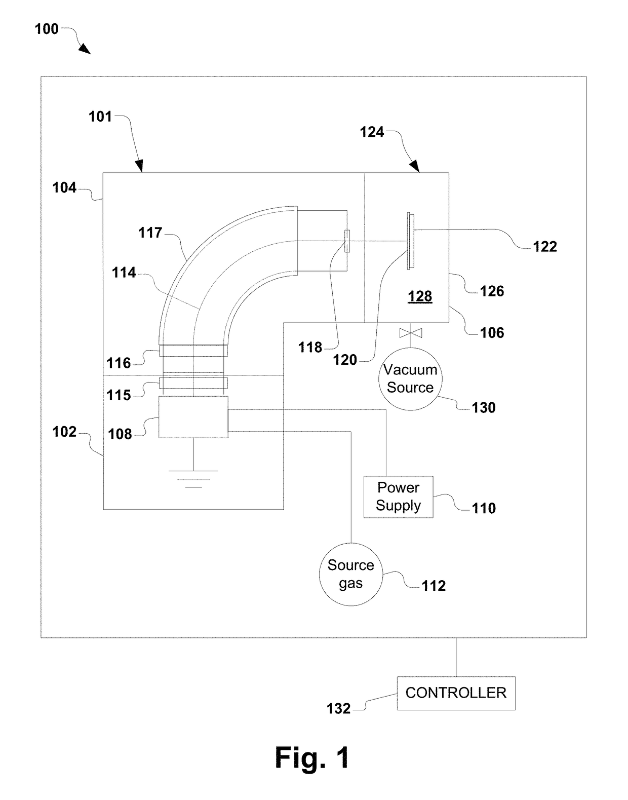
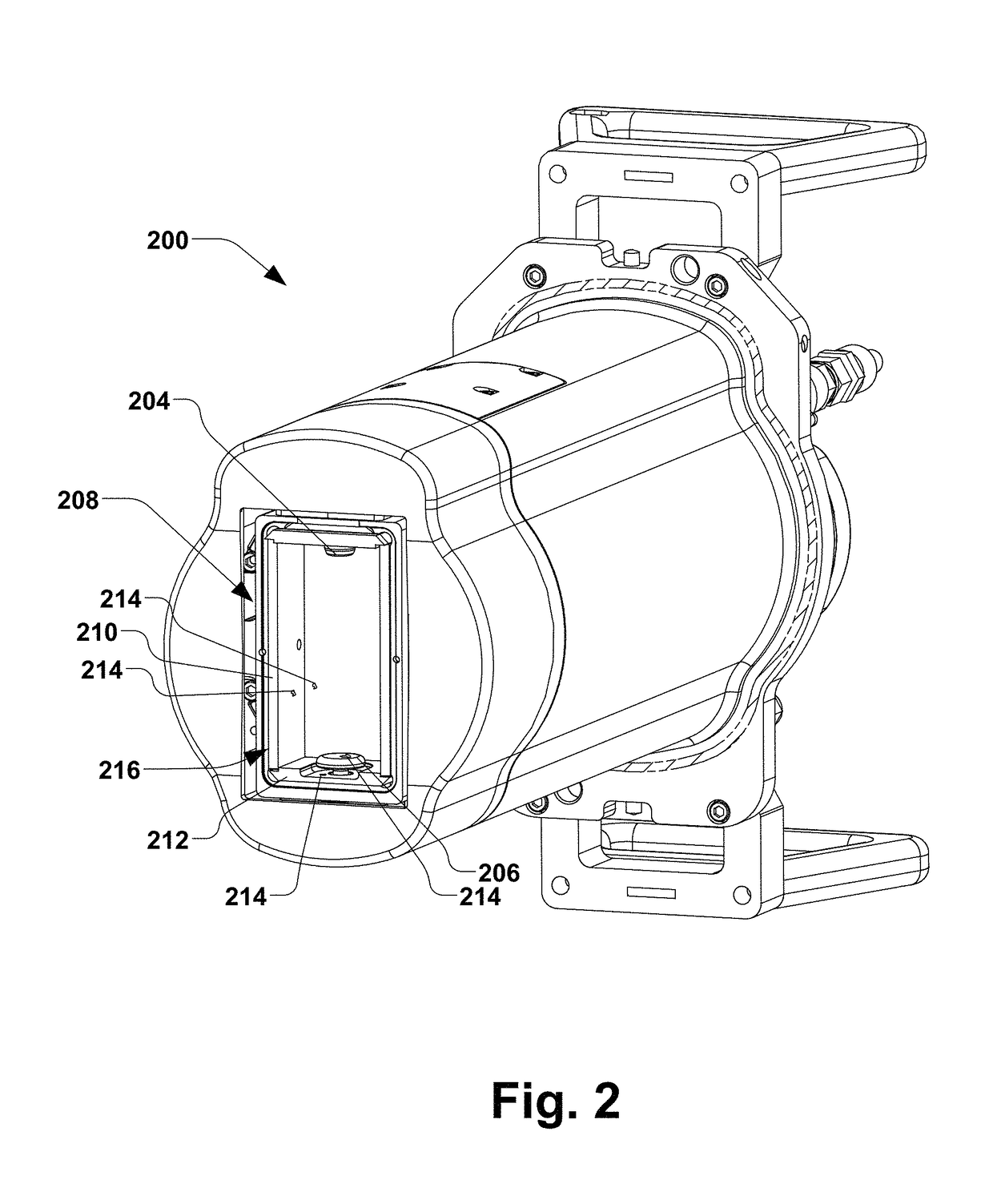
[0020]The present disclosure is generally directed toward carbon implantation utilizing a phosphorous trifluoride as co-gas with a carbon oxide gas. In one or more embodiments, carbon implantation with phosphorous trifluoride as the co-gas is in combination with an ion implantation system including at least one conductive component therein formed of lanthanated tungsten. Suitable carbon oxides include, without limitation, carbon monoxide, carbon dioxide, carbon suboxide, and the like, and mixtures thereof. In one or more embodiments, the ion source and beam line components utilized in the ion implantation system for carbon implantation includes surfaces or components formed of a lanthanated tungsten alloy for improved lifetime, stability, and operation of the ion implantation system. For carbon implantation, utilizing phosphorous trifluoride (PF3) as the co-gas with the carbon oxide, and in some embodiments, in combination with the lanthanated tungsten alloy ion source components ad...


PUM

PropertyMeasurementUnit
Percent by massaaaaaaaaaa
Weightaaaaaaaaaa
Massaaaaaaaaaa

Abstract

Processes and systems for carbon ion implantation include utilizing phosphorous trifluoride (PF3) as a co-gas with carbon oxide gas, and in some embodiments, in combination with the lanthanated tungsten alloy ion source components advantageously results in minimal oxidation of the cathode and cathode shield. Moreover, acceptable levels of carbon deposits on the arc chamber internal components have been observed as well as marked reductions in the halogen cycle, i.e., WFx formation.

Description


Claims


Application Information

Patent Timeline
Owner AXCELIS TECHNOLOGIES
Learn More