Digital wireless communication device and digital wireless communication system

a wireless communication and wireless communication technology, applied in diversity/multi-antenna systems, polarisation/directional diversity, independent non-interacting antenna combinations, etc., can solve the problems of increased installation and maintenance costs, increased installation costs, etc., and achieve the effect of heavy communication traffic and increased communication traffi

Inactive Publication Date: 2018-05-24
ATR ADVANCED TELECOMM RES INST INT +1
View PDF3 Cites 7 Cited by
  • Summary
  • Abstract
  • Description
  • Claims
  • Application Information

AI Technical Summary

Benefits of technology

[0032]According to the digital wireless communication device and the digital wireless communication system of the present invention, heavier communication traffic can be held in a linear cell using leaky coaxial cables.
[0033]Further, according to the digital wireless communication device and the digital wireless communication system of the present invention, heavier communication traffic can be held without increasing the cost of installing the leaky coaxial cables.

Problems solved by technology

According to the method disclosed in Non-Patent Literature 1, however, a plurality of LCXs must be arranged apart from each other so as to ensure sufficiently low correlation between each other, which leads to the problem of increased cost of installation and maintenance.
Therefore, cost of installation increases if the LCX becomes long.

Method used


Image

  • Digital wireless communication device and digital wireless communication system
  • Digital wireless communication device and digital wireless communication system
  • Digital wireless communication device and digital wireless communication system

Examples


embodiment 1

[0065](Outline of Wireless Communication System)

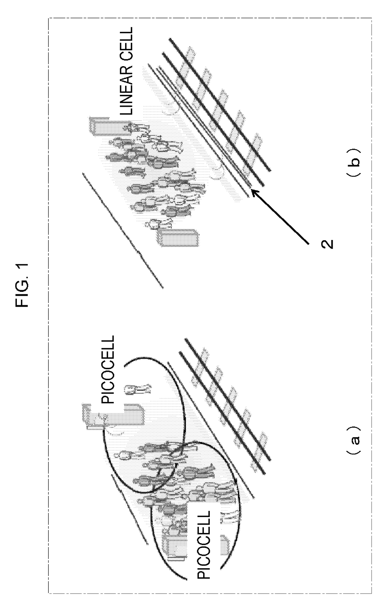
[0066]FIG. 1 includes illustrations showing the concept of linear cell in accordance with an embodiment.

[0067]When wireless communication is to be realized in an environment such as a railway platform as shown in (a) of FIG. 1, for example, conventionally, one wireless base station is provided per one picocell, and when a user having a terminal moves on the platform from one picocell to another, a handover process is necessary.

[0068]On the other hand, when a leaky coaxial cable 2 is used as an antenna as shown in (b) of FIG. 1, handover process and interference between cells can be avoided.

[0069]Further, as will be described later, in order to improve frequency use efficiency of an LCX system in an environment in which density of mobile terminals is so high as to cause communication traffic congestion, the system of FIG. 1(b) improves communication capacity of wireless communication using MIMO technique.

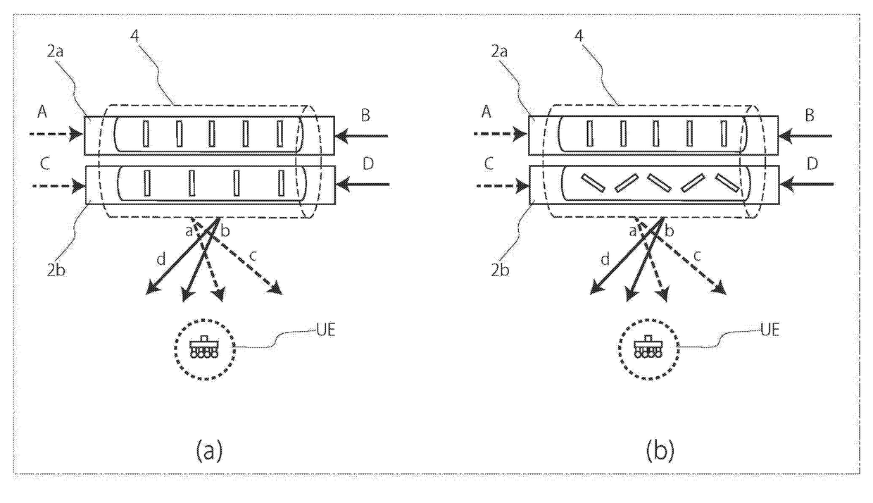
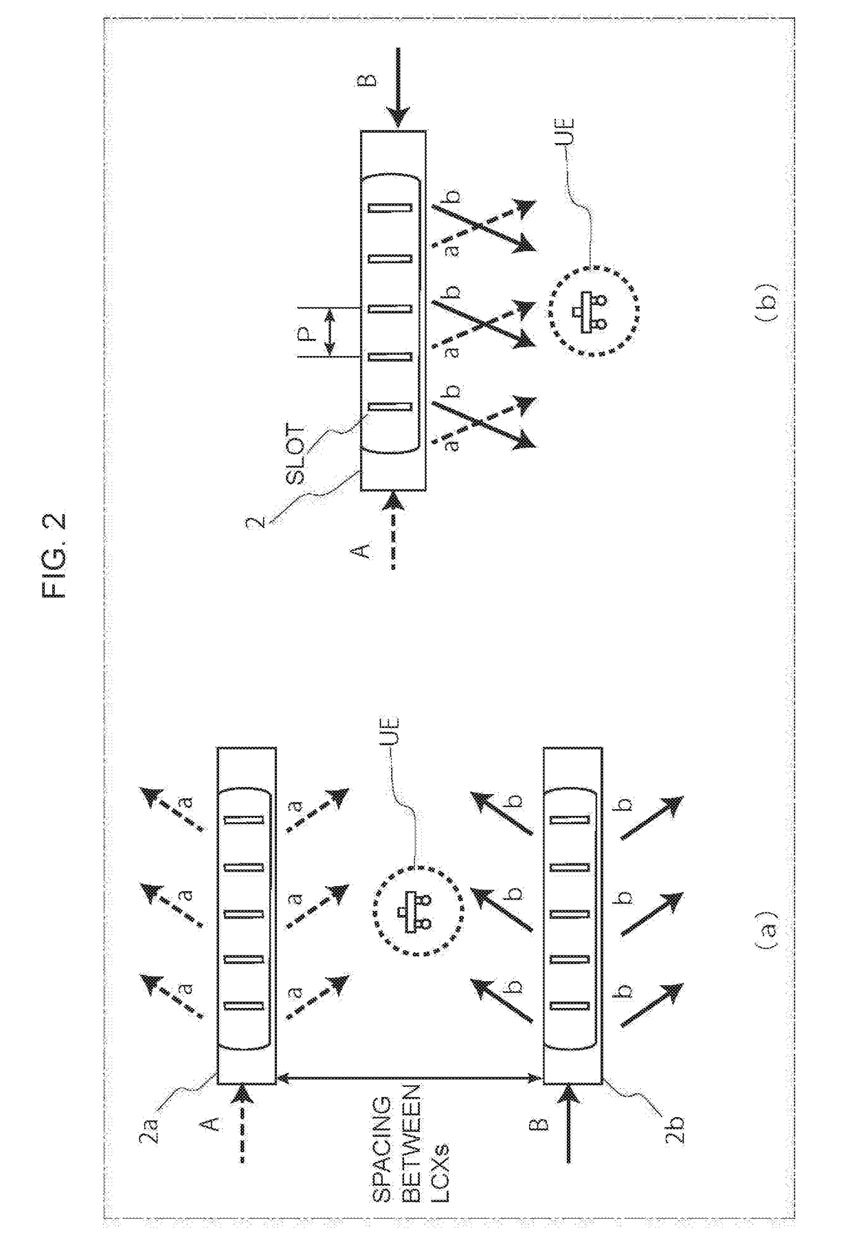
[0070]FIG. 2 includes illustrati...

embodiment 2

[0113]In Embodiment 2, a configuration for successfully realizing MIMO communication with the leaky coaxial cables structured by collectively housing a plurality of LCXs in one covering structure described in Embodiment 1 will be described in greater detail.

[0114]As already described with reference to FIG. 4, around inner conductor 200 on the central axis of LCX is provided insulator layer 202 having relative permittivity Around the outer circumference of insulator layer 202 is provided outer conductor 204, in which slots 206 are formed with a spacing P. On the outer circumference of outer conductor 204, covering structure 208 is provided.

[0115]As the covering structure, a sheath of plastic resin, for example, may be used. On outer conductor 204, elongate holes referred to as slots are formed to be arranged periodically, through which electromagnetic signals are transmitted / received between the inside of LCXs and the outer environment.

[0116](Radiation Principle and Radiation Angle)

[...


PUM


Abstract

A composite cable (4) houses a plurality of leaky coaxial cables having mutually different radiation characteristics. The leaky coaxial cable (2a, 2b) includes therein an inner conductor and an outer conductor, and has a plurality of leakage slots. The plurality of leakage slots have different slot periods relative to the axial direction or arranged in different slot patterns. The digital wireless communication device feeds a high-frequency signal from an end of the composite cable (4) and performs MIMO (multiple-input multiple-output) communication.

Description

TECHNICAL FIELD[0001]The present invention relates to a configuration of a wireless communication technique for digital communication between a mobile station and a ground station provided on the ground.BACKGROUND ART[0002]Mobile communication terminals such as smart phones are currently necessities of life, and communication traffic using these terminals has been increasing in buses, trains and air planes.[0003]On the other hand, a leaky coaxial cable (LCX) has been used as an antenna as a measure for communication in a dead zone such as tunnels and underground malls because of its advantages in connection stability. Further, since it is possible to provide communication range along the cable, its deployment to “linear cells” is also expected.[0004]Specifically, stable wireless network connection would be necessary at positions of arrangement over some long and narrow places referred to as the “linear cell” such as an area along a railway, tunnels, underground malls, shopping malls...

Claims


Application Information

Patent Timeline
Patent Type & Authority Applications(United States)
IPC IPC(8): H04B5/00H04B1/04H01Q13/22H04B7/04
CPCH01Q13/22H04B7/04H04B5/0018H04B1/0483H01Q13/203H01Q21/28H01Q25/004H04B7/0413H04B7/10
Inventor TSUKAMOTO, SATOSHIMAEDA, TAKAHIROHOU, YAFEIARIYOSHI, MASAYUKIKOBAYASHI, KIYOSHISUZUKI, FUMIONIWA, ATSUHIKO
Owner ATR ADVANCED TELECOMM RES INST INT
Why Eureka
Try Eureka