Internal planetary reduction gear

a technology of planetary reduction and gear, applied in the direction of gearing details, mechanical equipment, gearing, etc., can solve the problems of large speed reducer range, rv series speed reducer, and deterioration of degree of precision of speed reduction motion, etc., to achieve easy installation, reduce the range, and reduce the volume

Active Publication Date: 2018-05-31
SEJIN IGB
View PDF11 Cites 1 Cited by
  • Summary
  • Abstract
  • Description
  • Claims
  • Application Information

AI Technical Summary

Benefits of technology

[0018]According to the present inventive concept, since an input shaft can be easily installed without a constraint of penetrability of the input shaft or a

Problems solved by technology

However, the Teijin Seiki's RV series speed reducer has the following problems.
Thus, when the speed reducer is repeatedly operated, errors are accumulated and thus a degree of precision of a speed reduction motion deteriorates remarkably.
However, in order to apply the speed reducer to a low reduction ratio, separate components need to be added, and thus the speed reducer becomes large.
Third, since the 1-stage reduction gear is located at the output end, in order to prevent oil such as grease from leaking from a peripheral portion of the 1-stage reduction gear, a plurality of separate sealing components are provided on an outer circumferential surface of each 1-stage reduction gear, and thus the manufacturing costs and weight of the speed reducer are increased.
Fourth, as the 1-stage reduction gear are located at the output end side, while the size in a lengthwise direction of the insertion space in the input shaft to inert the drive shaft of the power source is guaranteed, the inner diameter of the insertion space may be quite limited due to the user of the pin gear.
In particular, a speed reducible range is much limited.
Sixth, since the pin gear is employed, the number of pi

Method used


Image

  • Internal planetary reduction gear
  • Internal planetary reduction gear
  • Internal planetary reduction gear

Examples


Embodiment Construction

Technical Problem

[0017]The present inventive concept provides an internal planetary reduction gear which may improve a reduction range compared to the related art, and reduce an installation volume as an input shaft can be easily installed without a constraint of penetrability of the input shaft or a condition of using a separate auxiliary structure.

Advantageous Effects

[0018]According to the present inventive concept, since an input shaft can be easily installed without a constraint of penetrability of the input shaft or a condition of using a separate auxiliary structure, an installation volume may be reduced and a reduction range may be improved compared to the related art.

DESCRIPTION OF THE DRAWINGS

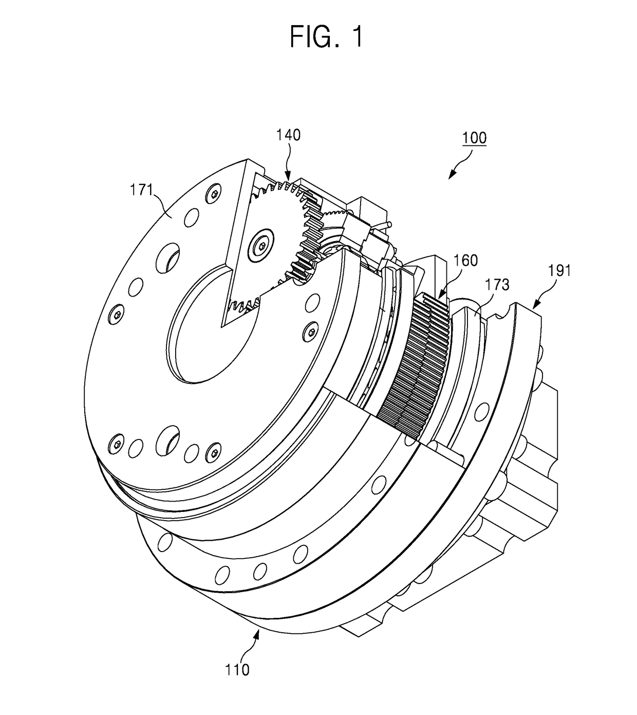
[0019]FIG. 1 is a partially cut-away perspective view of an internal planetary reduction gear according to an embodiment.

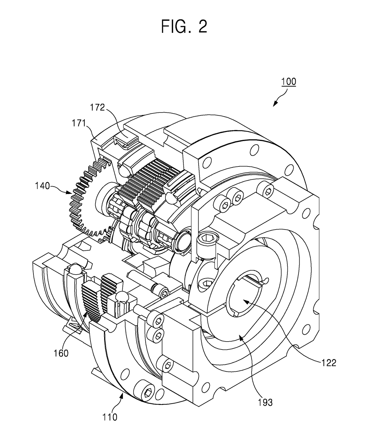
[0020]FIG. 2 illustrates FIG. 1 at a different angle.

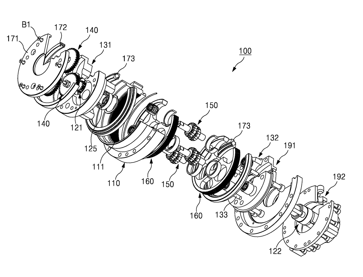
[0021]FIG. 3 is an exploded perspective view of FIG. 1.

[0022]FIG. 4 is an exploded perspective view of FIG. 2.

[0...


PUM


Abstract

Disclosed is an internal planetary reduction gear. The internal planetary reduction gear according to an embodiment of the present invention comprises: an internal-gear integrated main body that has an internal gear integrally formed on the inner wall thereof and is provided with a plurality of components for speed reduction; an input shaft module formed as a single body by coupling at least two separated parts with each other, wherein the input shaft module has an input gear formed on an end portion thereof and is connected to the internal-gear integrated main body to receive rotary power from a motor that is connected to the exterior of the internal-gear integrated main body; and an output shaft module that is connected to the input shaft module to interact therewith and reduces the speed of the rotary power of the motor, which is input from the input shaft module, to output the same.

Description

TECHNICAL FIELD[0001]The present inventive concept relates to an internal planetary reduction gear, and more particularly, to an internal planetary reduction gear which may improve a reduction range compared to the related art, and reduce an installation volume as an input shaft can be easily installed without a constraint of penetrability of the input shaft or a condition of using a separate auxiliary structure.BACKGROUND ART[0002]In general, automation and precision control apparatuses use a speed reducer (or a power transmission device) to reduce and transfer a rotational speed of a high load transferred via a drive shaft of a power source such as an electric motor, a servo motor, etc.[0003]Recently, as equipment becomes compact, a speed reducer is also required to be miniaturized while precisely operating.[0004]A speed reducer according to the related art includes RV series of Vigo Drive™ developed and sold by Teijin Seiki.[0005]The Teijin Seiki's RV series includes a plurality ...

Claims


Application Information

Patent Timeline
IPC IPC(8): F16H1/46F16H1/32H02K7/116
CPCF16H1/46F16H1/32H02K7/116F16H2001/323F16H57/023F16H2001/325F16H3/00F16H1/28F16H3/44
Inventor LIM, SUN HO
Owner SEJIN IGB
Why Eureka
Try Eureka