Touch sensor

Active Publication Date: 2018-05-31
LEE KYUNG YEON +1
View PDF0 Cites 1 Cited by
  • Summary
  • Abstract
  • Description
  • Claims
  • Application Information

AI Technical Summary

Benefits of technology

The present invention provides a touch sensor that can detect when a plunger is pushed into a main body case. This touch sensor is small in size, which makes it easier to place it in limited spaces. It is also efficient in dissipating heat, uses low power, and can quickly perform its sensing function regardless of the material of the detection object. The invention can achieve various benefits like labor force saving.

Problems solved by technology

Thus, to employ an expensive automatic tool changer or an automatic detection device having a complex structure, the entire volume of the end effector 50 is increased so that the size of a possible output is relatively reduced, thereby causing spatial restriction, inefficiency and heat in the end effector and the bed (working table).
Specifically, some non-contact sensors used for solving the above-described problems require that the detection object is formed of only a specific material such as metal, and cause a serious error even in the case of a detection object made of a material such as metal or glass.
In recent years, although there has been grown a demand for an automatic detection function in order to speed up work, improve efficiency, and reduce labor force, there have been many difficulties in automation due to the above-described problems.

Method used


Image

  • Touch sensor
  • Touch sensor
  • Touch sensor

Examples


Embodiment Construction

[0056]Hereinafter, an embodiment of the present invention will be described in detail with reference to accompanying drawings as follows.

[0057]However, the dimensions, materials, shapes, relative arrangements and the like of the constituent parts described in the present embodiment are not intended to limit the scope of the present invention and are merely illustrative examples, unless otherwise specified.

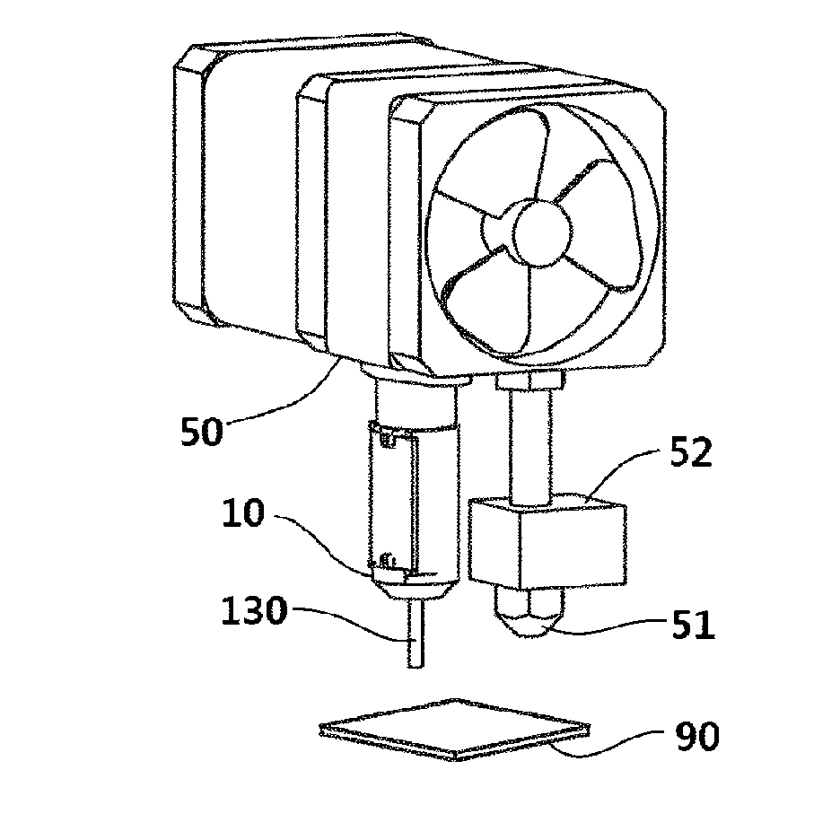
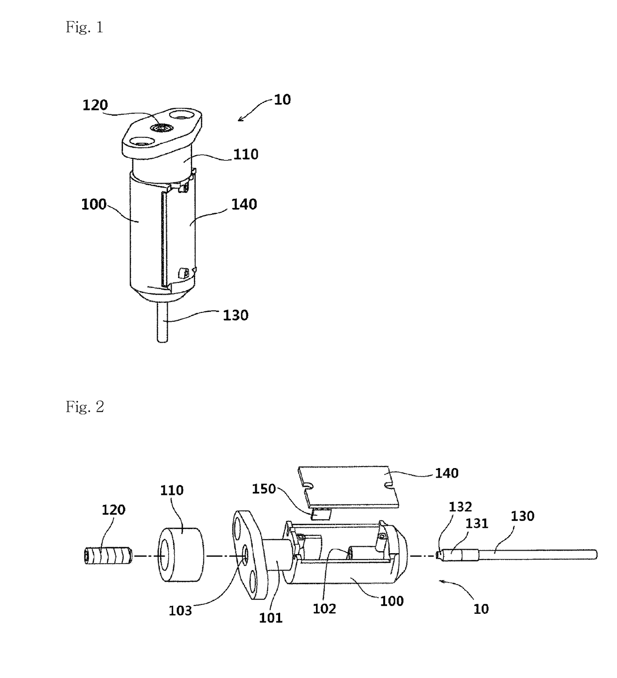
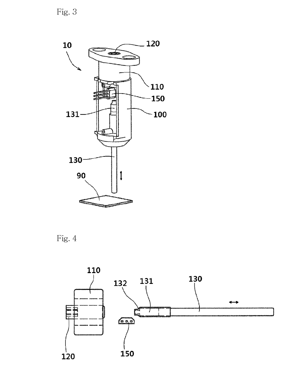
[0058]FIG. 1 is a perspective view illustrating a touch sensor according to an embodiment of the present invention. FIG. 2 is an exploded perspective view illustrating a touch sensor according to an embodiment of the present invention. FIG. 3 is a view illustrating the internal operation of the touch sensor of FIG. 1. FIG. 4 is a view illustrating a state in which the plunger of a touch sensor according to an embodiment of the present invention is moved to an outside. FIG. 5 is a view illustrating a state in which the plunger of the touch sensor of FIG. 4 enters the inside of the t...


PUM


Abstract

The present invention relates to a touch sensor and, more particularly, to a touch sensor having a solenoid provided therein, wherein the touch sensor: after a plunger is pushed out of a main body case thereof when a detected start command is input, detects the plunger being pushed into the main body case by means of a detected object (bed) and generates a detection signal; and when a detection end command is input, allows the plunger to be pushed in, thereby removing hindering elements that arise and solving spatial limitations while 3D printing or operating machine tools. Also, the touch sensor is capable of carrying out a detecting function quickly and at a low power consumption and enables manpower to be reduced.

Description

TECHNICAL FIELD[0001]The present invention relates to a touch sensor and, more particularly, to a touch sensor having a solenoid provided therein, wherein the touch sensor: after a plunger is pushed out of a main body case thereof when a detection start command is input, detects the plunger being pushed into the main body case by means of a detected object (bed) and generates a detection signal; and when a detection end command is input, allows the plunger to be pushed in, thereby removing hindering elements that occur while a 3D printer or a machine tool is operated, reducing the installation space and allowing the 3D printer or machine tool to be effectively operated.BACKGROUND ART[0002]A 3D printer or a machine tool according to the related art is required to exchange a tool of an end effector or attach a touch sensor including a device such as a servo motor, an actuator, a servo arm, a touch switch, a proximity sensor, and the like thereto to detect a horizontality or position o...

Claims


Application Information

Patent Timeline
IPC IPC(8): G01B5/14B33Y50/02
CPCG01B5/14B33Y50/02H01H3/28H01H36/00H01H35/00
Inventor LEE, KYUNG YEONLEE, CHUL HEE
Owner LEE KYUNG YEON
Why Eureka
Try Eureka