Fuel cell system
a fuel cell and system technology, applied in the field of fuel cell systems, can solve problems such as unstable electricity generation
- Summary
- Abstract
- Description
- Claims
- Application Information
AI Technical Summary
Benefits of technology
Problems solved by technology
Method used
Image

Examples
embodiments
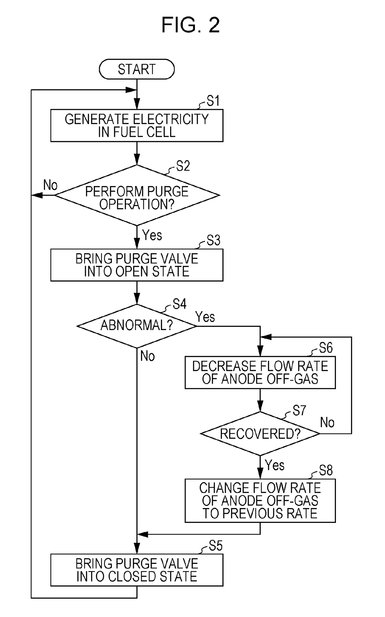
[0025]A fuel cell system according to a first aspect of the present disclosure includes: a fuel cell that generates electricity by an electrochemical reaction of a fuel gas supplied to an anode with an oxidant gas supplied to a cathode; a supply channel that supplies the fuel gas to the anode; a recycle channel that supplies an anode off-gas discharged from the anode, as the fuel gas, to the supply channel; a circulation pump that is arranged in the recycle channel; a discharge channel that is connected to the recycle channel between the anode and the circulation pump and that discharges the anode off-gas to outside; a purge valve that is provided on the discharge channel; and a controller, in which the controller determines whether a purge operation in which the purge valve is brought into an open state to discharge the anode off-gas to the outside is abnormal, and when the controller determines that the purge operation is abnormal, the controller performs a decreasing operation to...
first embodiment
[Configuration of Apparatus]
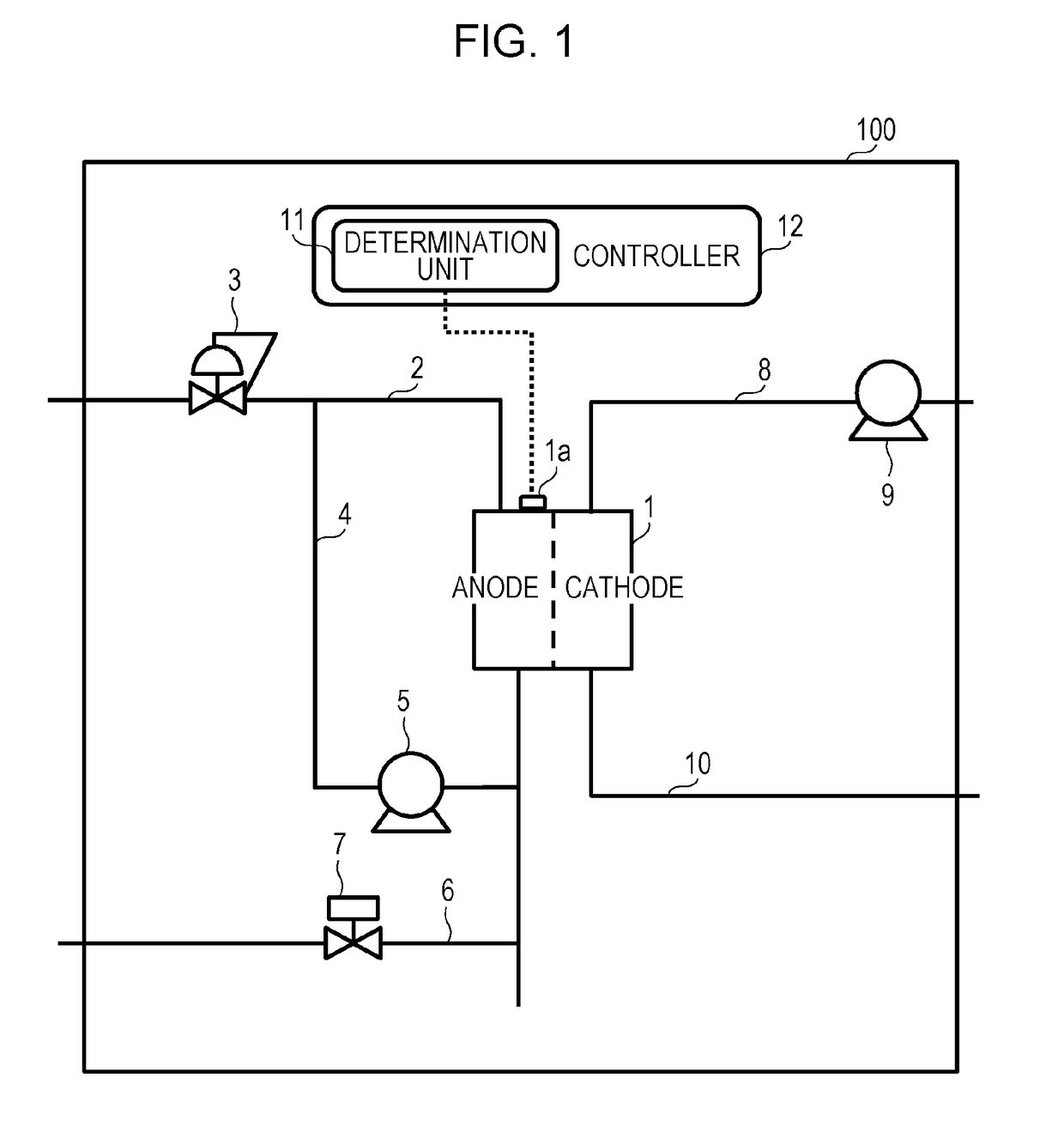
[0037]First, a configuration of a fuel cell system 100 according to a first embodiment is described with reference to FIG. 1. The fuel cell system 100 includes a fuel cell 1 that generates electricity by an electrochemical reaction of a fuel gas supplied to an anode with an oxidant gas supplied to a cathode, a supply channel (a first supply channel) 2 that supplies the fuel gas to the anode, a supply channel (a second supply channel) 8 that supplies the oxidant gas to the cathode, and a controller 12 that controls the units.
[0038]The fuel cell system 100 includes a discharge channel (a first discharge channel) 6 that discharges an anode off-gas discharged from the anode to the outside and a discharge channel (a second discharge channel) 10 through which a cathode off-gas discharged from the cathode flows. The fuel cell 1 uses hydrogen in the fuel gas to generate electricity. Since the anode off-gas discharged from the fuel cell 1 still contains hydrogen, ...
first modification
of First Embodiment
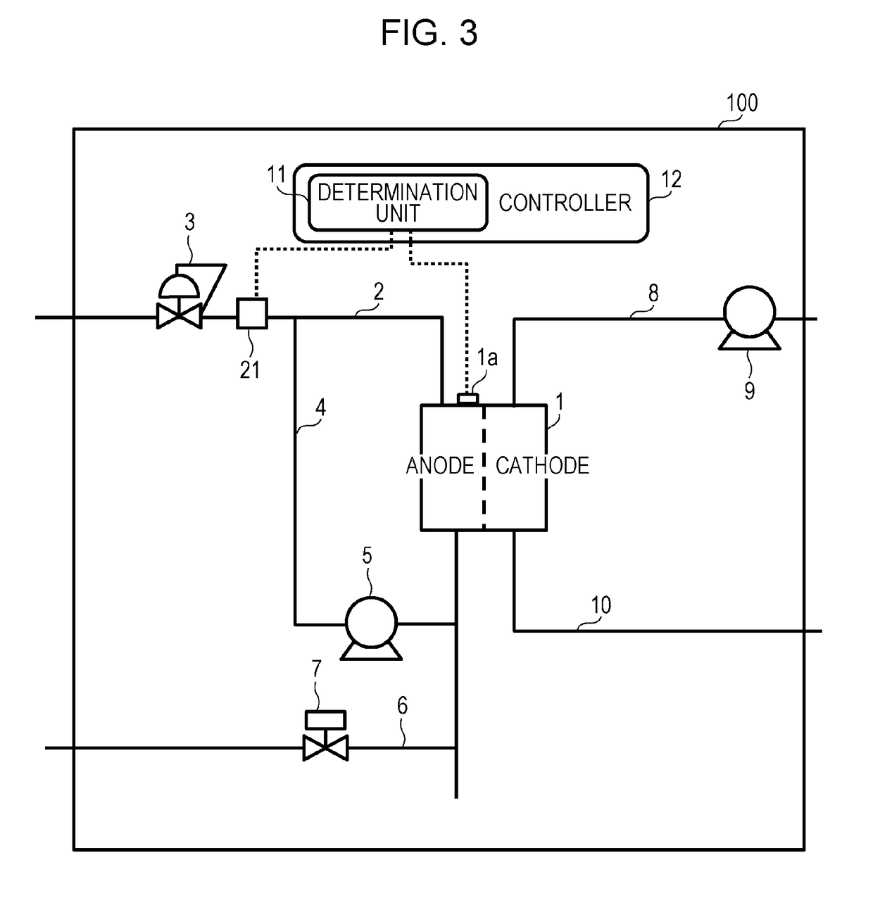
[0066]Next, a configuration of the fuel cell system 100 according to a first modification of the first embodiment is described with reference to FIG. 3. The fuel cell system 100 of the first modification further includes a flow rate detector 21 provided in the first supply channel 2. The determination unit 11 determines that the purge operation is abnormal when the flow rate during the purge operation is below a predetermined flow rate. Other configurations, workings, and effects are the same as those of the fuel cell system 100 illustrated in FIG. 1; thus, descriptions thereof are omitted.
[0067]The flow rate detector 21 is provided in the first supply channel 2 on the upstream side of the point connected with the recycle channel 4. The flow rate detector 21 detects the flow rate of the fuel gas before being mixed with the anode off-gas in the recycle channel 4 and outputs the detected value to the controller 12. As the flow rate detector, for example, a flow rate...
PUM
| Property | Measurement | Unit |
|---|---|---|
| flow rate | aaaaa | aaaaa |
| voltage | aaaaa | aaaaa |
| concentration detector | aaaaa | aaaaa |
Abstract
Description
Claims
Application Information
 - R&D
- Intellectual Property
- Life Sciences
- Materials
- Tech Scout
- Unparalleled Data Quality
- Higher Quality Content
- 60% Fewer Hallucinations
Browse by: Latest US Patents, China's latest patents, Technical Efficacy Thesaurus, Application Domain, Technology Topic, Popular Technical Reports.
© 2025 PatSnap. All rights reserved.Legal|Privacy policy|Modern Slavery Act Transparency Statement|Sitemap|About US| Contact US: help@patsnap.com