
Vtol aircraft with wings

a technology of vtol aircraft and wings, which is applied in the direction of wing shape, vertical landing/take-off aircraft, wing adjustment, etc., can solve the problems of few matured models encountering a lot of accidents, machines are broken, and the vtol airplane cannot perform some important maneuvers, etc., to save energy, save weight, and land safely

Active Publication Date: 2018-06-07
CHANG JIANN CHUNG
View PDF26 Cites 1 Cited by
  • Summary
  • Abstract
  • Description
  • Claims
  • Application Information

AI Technical Summary

Benefits of technology

The present invention is about a VTOL aircraft that can take off and land stably, and save energy during level flight. The design of the aircraft allows for low drag when landing or taking off, and high efficiency during cruising or gliding. This means that the aircraft can save more energy and operate at higher efficiency compared to traditional methods. Additionally, even if one or more thrust units fail during flight, the aircraft can still glide safely.

Problems solved by technology

Because the idea of minimizing the sizes of wings of VTOL airplane is abandoned and the idea of controlling the wings of VTOL airplane is dismissed, the contemporary VTOL airplane cannot perform some important maneuver, such as gliding.
Such configurations of lifting and pulling in an active way to support an aircraft, such as a tilt-rotor or quadcopter, are incapable of inducing both lift and thrust at the same time, and are so vulnerable that the machines are broken.
A few matured models encounter a lot of accidents.
Such design always faces safety issue challenge.
A helicopter is inferior to an airliner in range, safety and fuel consumption efficiency, which restricts itself to special transportation applications only.
When most of the energy of thrust is used to create lift to overcome gravity, it will consume lots of energy and limit flight range, too.
That will be a huge disadvantage when industry pursues large battery or fuel cell volume for acceptable flight distance.
Considering there is a huge VTOL fleet under service, the energy saving will turn to be an unavoidable issue and be examined.
Nevertheless, the safety of the tilt rotor airplane is not insured by the industry after so many accidents have happened because of active lift disequilibrium caused by mechanical failure.
The latter type utilizes redundancy idea to overcome the safety problem but does not have any energy saving solution during a long distance flight by electrical propulsion's poor efficient nowadays.

Method used


Image

  • Vtol aircraft with wings
  • Vtol aircraft with wings
  • Vtol aircraft with wings

Examples


Embodiment Construction

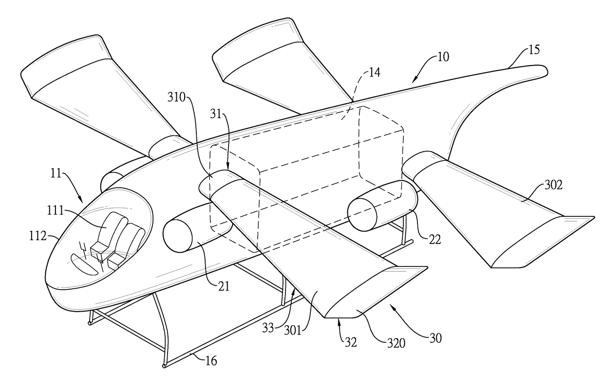
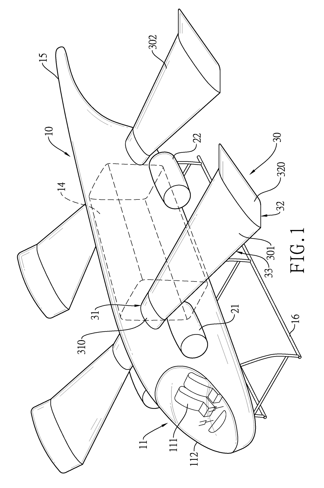
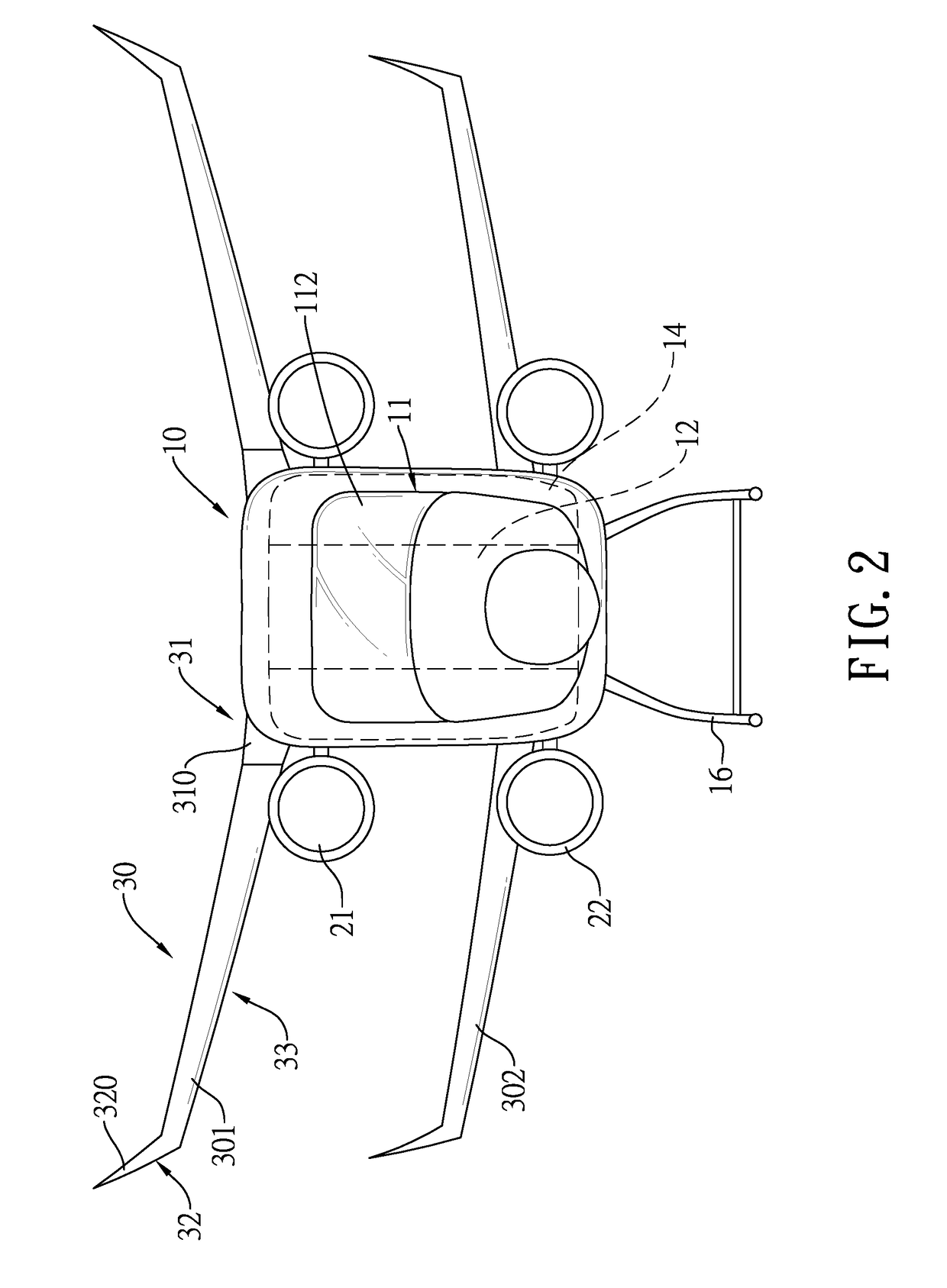
[0030]Please refer to FIGS. 1 to 4. A vertical taking-off and landing (hereinafter referred to as VTOL) aircraft comprises a fuselage 10, a plurality of pairs of thrust units, and at least one pair of wings.

[0031]In a first embodiment, the fuselage 10 of the VTOL aircraft comprises a pilot cabin 11, a passage 12, two transmission chambers 13, a payload cabin 14, a tail rod 15, and a landing truss 16. The fuselage 10 has a length direction.

[0032]The pilot cabin 11 is located at a front end of the fuselage 10 and comprises two abreast seats 111 and a window 112. The two abreast seats 111 are juxtaposed and mounted in the pilot cabin 11. The window 112 is in front of the abreast seats 111 and extends to two sides of the two abreast seats 111. In other words, rear edges of the window 112 are behind pilots, which causes pilots' view angle θ in the pilot cabin 11 to be over 180 or 270 degrees horizontally as shown in FIG. 4.

[0033]The passage 12 is spaced apart from the abreast seats 11 an...


PUM


Abstract

A VTOL aircraft is provided with a fuselage, a pair of first thrust units, a pair of second thrust units, and a pair of first wings. The first thrust units and the second thrust units are tiltably mounted on the fuselage. The first wings are securely mounted on the fuselage, and each first wing has a root end and an outer end. The longitudinal length of the outer end is larger than that of the root end. Thus, when the VTOL aircraft is landing or taking off, the airflow can pass around the root ends of the first wings; when the VTOL aircraft is cruising or gliding, the wings can provide lift, so that the first thrust units and the second thrust units can operate in a low mode, which makes the VTOL aircraft save energy and land safely even when the thrust units are broken.

Description

BACKGROUND OF THE INVENTION1. Field of the Invention[0001]The present invention relates to an air vehicle, especially to a vertical taking-off and landing (hereinafter referred to as VTOL) aircraft.2. Description of the Prior Arts[0002]Contemporary in-service or experimental VTOL aircrafts rely on thrust continuously contributed from propellers or jet flow in an opposite direction of gravity to maintain the airborne. Their lift is generated by two, four or more numbers of thrust units. Gravity at a center of vertical taking off and landing is supported stably through those vertical thrust units equipped evenly. For safety consideration, some announced designs utilize redundancy thrust units to avoid any chance that a stability of a lift system for supporting an aircraft is broken. Afterwards, both longitudinal and lateral thrust forces are controllable and stable, too. The forward flight driven thrust is obtained by adjusting an angle of shafts of thrusts with respect to a horizonta...

Claims


Application Information

Patent Timeline
IPC IPC(8): B64C29/00B64C3/38
CPCB64C3/38B64C29/0008B64C3/10B64C29/0075B64C39/08Y02T50/10
Inventor CHANG, JIANN-CHUNG
Owner CHANG JIANN CHUNG
Learn More