Electric Heating Device and PTC Heating Element of an Electric Heating Device

a heating element and heating device technology, applied in lighting and heating apparatus, ohmic resistance waterproof/air tight seals, and immersion heating arrangements

Active Publication Date: 2018-06-07
EBERSPACHER CATEM
View PDF24 Cites 10 Cited by
  • Summary
  • Abstract
  • Description
  • Claims
  • Application Information

AI Technical Summary

Benefits of technology

[0024]According to a preferred development of the present invention, the plastic frame is provided with a tapered abutment ridge on its outer side. This abutment ridge is formed to be tapering in the thickness direction of the plastic frame. The abutment ridge is commonly provided at least on a frame tie of the plastic frame. Particularly preferably, the abutment ridge is provided on three successive outer sides or frame ties of the plastic frame. On the side of the plastic frame which is disposed opposite to the contact surfaces, the bottom abutment ridge forms a seal against the base of a heating device casing. The edge-side abutment ridges, which extend at a right angle thereto, serve to seal against a lateral wall of the heating device casing. The PTC elements can be provided in an alternately staggered manner so that each first PTC heating element abuts against, for example, a left side on the heati...

Problems solved by technology

Although such an embodiment represents a simplification in terms of production technology as compared to the previously described prior art, the design is still relatively bulky and complex.
Furthermore, good heat decoupli...

Method used


Image

  • Electric Heating Device and PTC Heating Element of an Electric Heating Device
  • Electric Heating Device and PTC Heating Element of an Electric Heating Device
  • Electric Heating Device and PTC Heating Element of an Electric Heating Device

Examples


second embodiment

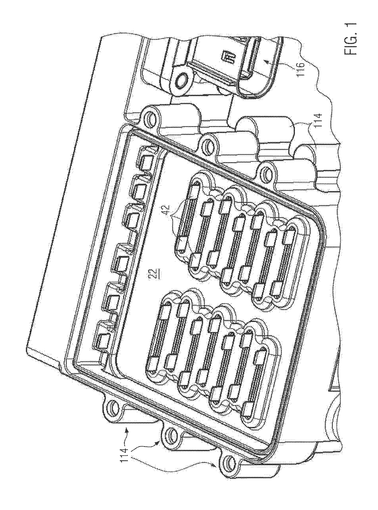
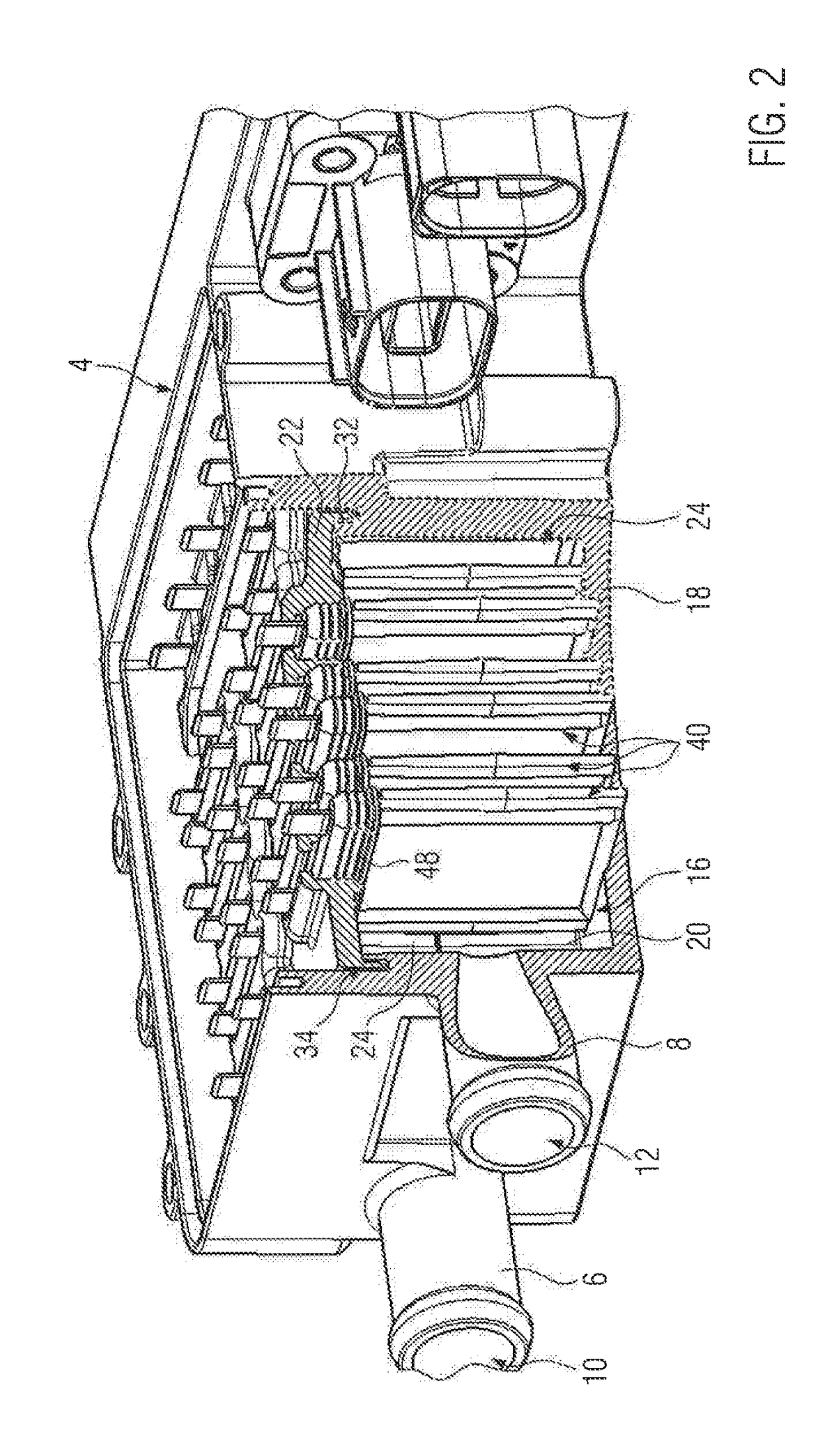
[0042]FIG. 1 shows a perspective top view of a casing, designated by reference numeral 2, of an electric heating device configured as a water heater. The casing 2 has a casing tub element 4 made of plastic material. This plastic material is presently duroplastic material. The casing 2 forms an inlet port 6 and an outlet port 8 which are presently embodied formed integrally on the casing tub element 4. The ports 6, 8 are designed as hose connection ports and form an inlet opening 10 and an outlet opening 12, respectively, to a circulation chamber designated by reference numeral 14. The circulation chamber 14 is divided into two heating chambers, of which only the heating chamber 16 shown in the front of the representation can be seen in FIGS. 1 and 2. The circulation chamber 14 is divided by a dividing wall 20, which is formed integrally on the casing tub element 4 and protrudes inwardly from the base 18 thereof, and which is continued by a further dividing wall 24 identified by refe...

first embodiment

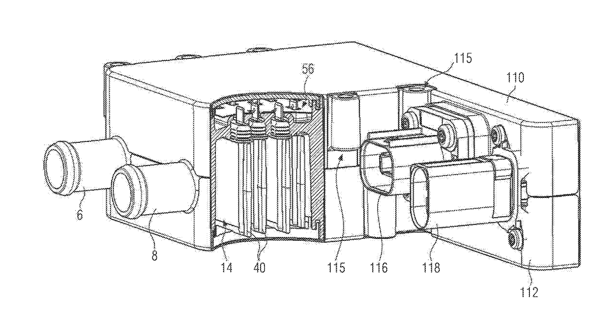
[0047]FIG. 5 in a sectional view illustrates the nature of an embodiment of a casing base member which is designated by reference numeral 50. The casing base member 50 forms walls that are designated by reference numerals 52 and surround the circulation chamber 16 circumferentially, i.e. the heating chambers 16 and the connection channel 26. The cover plate 22, which is provided as a separate component in the previously described embodiment, is presently embodied integrally with the casing base member 50 and presently also forms a partition wall 54, like in the first embodiment, which separates the circulation chamber 16 from a connection chamber 56 in which presently all contact strips 42 of all the PTC heating elements 40 are exposed. Walls designated by reference numeral 58 and surrounding the connection chamber circumferentially are also formed by the casing base member 50. Finally, in the extension of the ports 6, 8 and in this direction behind the circulation chamber 16 or the...


PUM


Abstract

An electric heating device a PTC heating element, a platelet-type PTC element which has two main side surfaces and face side surfaces extending perpendicular to the main side surfaces, and a casing. The casing forms inlet and outlet openings for the fluid to be heated and forms a circulation chamber in which a heat emitting surface of the PTC heating element is exposed and is coupled in a heat conductive manner to the PTC element. The PTC element is contacted in an electrically conductive manner by way of electrical conductor tracks to different polarities. A high degree of efficiency and a high output is obtained in that the conductor tracks are contacted in an electrically conductive manner to face side surfaces of the PTC element.

Description

BACKGROUND OF THE INVENTION1. Field of the Invention[0001]The present invention relates to an electric heating device including a PTC heating element and a PTC element housed in a plastic casing,2. Description of the Related Art[0002]Such an electric heating device is known from EP 2 607 121 A1. Accommodated in a positioning frame forming the heating element casing are several PTC elements which are contacted on oppositely disposed main side surfaces by a contact plate, which are locked to the positioning frame. At one face side, connection ports project beyond the heating element casing and are integrally formed on the heating element casing and sealing sleeves made of Teflon with a labyrinth seal provided on the outer peripheral surface are drawn over the connection ports. Insulation layers formed from plastic film are respectively applied to the outer side of the contact plates facing away from the PTC elements.[0003]Similar PTC heating elements are known from EP 1 253 808 A1 and...

Claims


Application Information

Patent Timeline
IPC IPC(8): F24H9/20F24H1/10H05B1/02
CPCF24H9/2028F24H1/103H05B1/0244H05B2203/02F24H1/202F24H9/1827H05B3/32F24H9/1818F24H9/1863F24H9/2014F24H9/2071H05B3/04H05B3/146H05B3/14B60H1/2221F24H1/102H05B3/03H05B3/10H05B3/82H05B2203/021F24H2250/04H05B1/0236H05B3/24F24H1/009F24H1/121F24H9/1872H05B2203/023F24H3/0429B60H1/2215B60H1/2225B60H2001/2278H05B3/02H05B3/141H05B3/06
Inventor BOHLENDER, FRANZSCHWARZER, ANDREAS
Owner EBERSPACHER CATEM
Why Eureka
Try Eureka