Current detection device

Inactive Publication Date: 2018-06-07
KOA CORP
View PDF3 Cites 6 Cited by
  • Summary
  • Abstract
  • Description
  • Claims
  • Application Information

AI Technical Summary

Benefits of technology

[0007]According to the present invention, the unit metal member includes a resistor body and a pair of voltage terminals to obtain a voltage signal produced between both ends of the resistor body, and a plural of the unit metal members is held by the holding member in parallel. Therefore, when detecting a 3-phase motor current, w

Problems solved by technology

Further, it is necessary to install a magnetic shielding so that adjacent wiring is mutually unaff

Method used


Image

  • Current detection device
  • Current detection device
  • Current detection device

Examples


Example

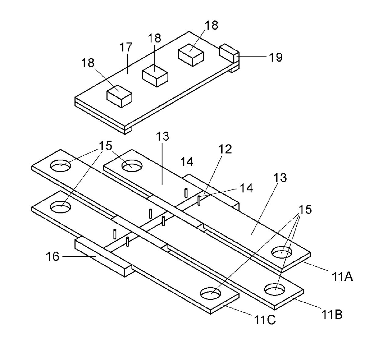
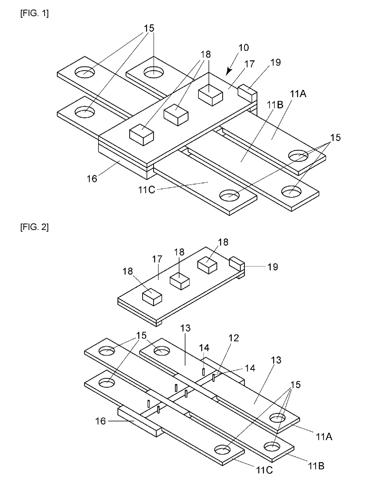
[0016]FIGS. 1-3 illustrate a current detection device of the embodiment 1. The device 10 detects 3-phase currents such as for driving a 3-phase AC motor etc. The device 10 is used so as to be inserted between outputs of an inverter circuit and inputs of a motor M (see FIG. 7). That is, three unit metal members (shunt resistors) 11A,11B,11C, through which currents to be detected pass, are inserted in a current route between outputs of an inverter circuit, which supplies driving currents, and U-phase, V-phase, and W-phase inputs of a 3-phase AC motor.

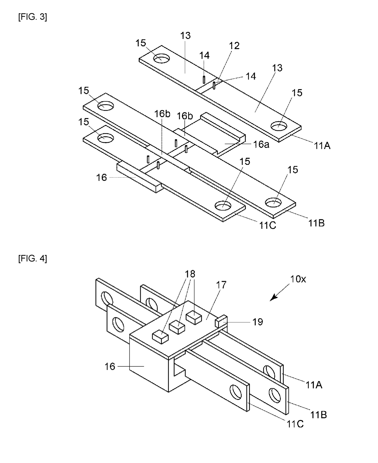
[0017]Each shunt resistor 11A, 11B, 11C is provided with a resistor body 12 and electrodes (terminal members) 13 fixed at both ends of the resistor body 12 (see FIGS. 2-3). The resistor body 12 consists of metal material such as Cu—Mn system alloy, Cu—Ni system alloy, or Ni—Cr system alloy etc., which has a far smaller temperature coefficient of resistance than Cu etc. The electrode (terminal member) 13 consists of high conductivity metal...

Example

[0026]FIGS. 4-6 illustrates a current detection device of the embodiment 2. In the current detection device 10x, the holding member 16 holds the unit metal members (shunt resistors) 11A,11B,11C disposed in parallel in the direction of thickness direction. As a result, the current detection device 10x can be smaller.

[0027]In the embodiment, the concave portion 16a is formed for holding a plate shaped shunt resistor in the direction of thickness direction. A portion including the resistor body 12 of the unit metal member (shunt resistor) 11A,11B,11C is accommodated in the concave portion 16a. And, a plural of the unit metal resistors (shunt resistor) corresponding to 3-phases is held in the holding member 16. Convex portions 16b are formed between the concave portions 16a in the holding member 16 so that electrical insulation is secured between adjacent shunt resistors (see FIG. 6).

[0028]On the back surface of the board 17, a spacer 20, which holds the shunt resistors at an interval, ...


PUM


Abstract

Provided is a compact and easily mountable current detection device in which a resistor body can be easily inserted in a current path, and a voltage value produced by the current can be easily obtained. The current detection device comprises a unit metal member (11A, 11B, 11C) that pass a current to be detected, a pair of voltage terminals (14, 14), which obtain a voltage signal from the unit metal member, and a holding member (16) that holds a plural of the unit metal members in parallel. A plural of the unit metal members (11A, 11B, 11C) is interposed between the holding member (16) and the board (17) on which a plural of wiring patterns is formed, and each pair of the voltage terminals (14, 14) of the unit metal member is connected to each wiring pattern formed on the board.

Description

TECHNICAL FIELD[0001]The present invention relates to a current detection device, which detects a current by using a shunt resistor, especially suitable to detect a 3-phase current detection, such as for a 3-phase AC motor current for driving the motor installed in a motor vehicle etc.BACKGROUND ART[0002]For detecting a current, which drives a 3-phase AC motor etc., for example, a magnetic detection method such as using a hall element is conventionally used. However, in the magnetic detection method, a structure that current wiring is passed through a core consisting of magnetic material is required. Further, it is necessary to install a magnetic shielding so that adjacent wiring is mutually unaffected. Therefore, there is a problem that the current detection device itself becomes a large-scale.[0003]On the other hand, a current detection device, which uses a shunt resistor for detecting a current for driving a 3-phase AC motor etc. by detecting a voltage caused by the current passi...

Claims


Application Information

Patent Timeline
IPC IPC(8): G01R19/00
CPCG01R19/0092G01R31/42G01R1/203
Inventor NAKAMURA, KEISHIOSAWA, RYOTOYODA, SUSUMUKAMEKO, KENJISHINODA, KAORU
Owner KOA CORP
Why Eureka
Try Eureka