Vacuum hold-down of seamless image panel to polycarbonate protective frontplane

Active Publication Date: 2018-06-07
PRYSM SYST INC
View PDF1 Cites 1 Cited by
  • Summary
  • Abstract
  • Description
  • Claims
  • Application Information

AI Technical Summary

Benefits of technology

[0006]The disclosure described herein generally relates to an image panel and a method of compressing the image panel. A breather assembly is coupled to at least one edge of the image panel and a vacuum is drawn through the breather assembly to pull the image panel portion and the front panel into intimat

Problems solved by technology

Due to the rolling and/or the air pockets, the image panel portion and the f

Method used


Image

  • Vacuum hold-down of seamless image panel to polycarbonate protective frontplane
  • Vacuum hold-down of seamless image panel to polycarbonate protective frontplane
  • Vacuum hold-down of seamless image panel to polycarbonate protective frontplane

Examples


Embodiment Construction

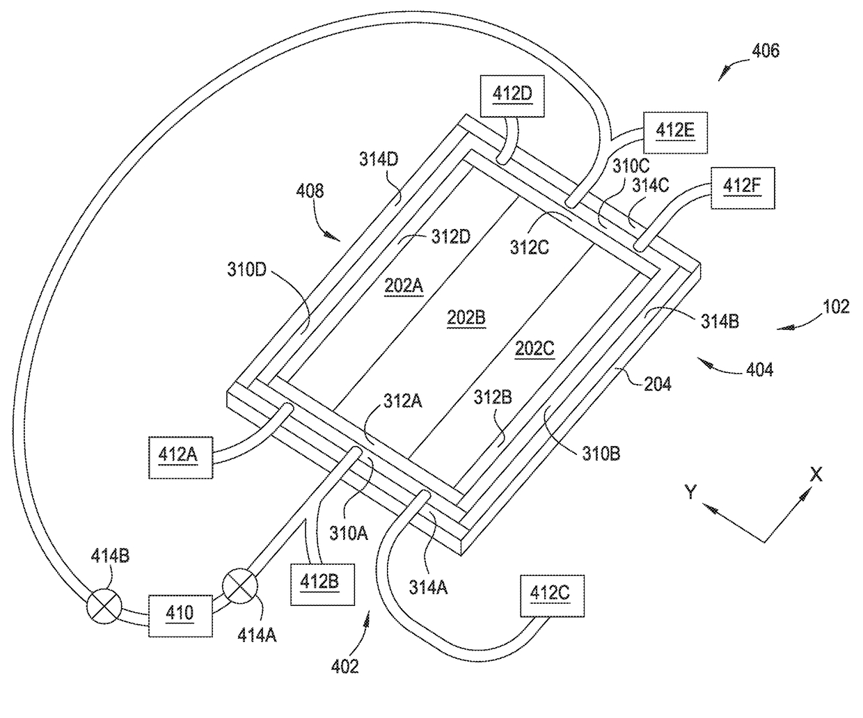
[0017]The disclosure described herein generally relates to an image panel and a method of compressing the image panel. A breather assembly is coupled to at least one edge of the image panel and a vacuum is drawn through the breather assembly to pull the image panel portion and the front panel into intimate contact with phosphors sandwiched therebetween. The breather assembly draws the vacuum from the air pockets between adjacent phosphors to pull the image panel flat and thus prevent image artifacts from forming while also permitting the image panel portion and the front plane panel to move independently.

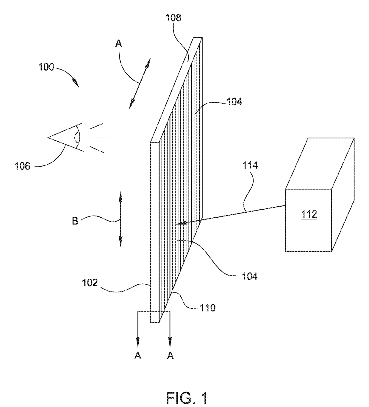
[0018]FIG. 1 is a perspective schematic diagram of a display system 100, according to embodiments of the disclosure. Display system 100 is a light-based electronic display device configured to produce video and static images for a viewer 106. The display system 100 includes light-emitting phosphors 104 disposed between two planes. For example, display system 100 may be a LPD or othe...


PUM

PropertyMeasurementUnit
Pressureaaaaaaaaaa
Pressureaaaaaaaaaa
Pressureaaaaaaaaaa

Abstract

The disclosure described herein generally relates to an image panel and a method of compressing the image panel. A breather assembly is coupled to at least one edge of the image panel and a vacuum is drawn through the breather assembly to pull the image panel portion and the front panel into intimate contact with phosphors sandwiched therebetween. The breather assembly draws the vacuum from the air pockets between adjacent phosphors to pull the image panel flat and thus prevent image artifacts from forming while also permitting the image panel portion and the front plane panel to move independently.

Description

CROSS-REFERENCE TO RELATED APPLICATIONS[0001]This application claims benefit of U.S. Provisional Patent Application Ser. No. 62 / 430,240, filed Dec. 5, 2016, which is herein incorporated by reference.BACKGROUNDField[0002]Embodiments of the present disclosure generally relate to drawing a vacuum between two panels of a display device.Description of the Related Art[0003]Electronic display systems are commonly used to display information from computers and other sources. Typical display systems range in size from small displays used in mobile devices to very large displays, such as tiled displays, that are used to display large size images and video. Tiled display systems are generally made up of multiple smaller individual display devices, or “tiles”, that are carefully aligned when assembled to provide a seamless and uniform appearance. In some embodiments, each tile may be a light-based electronic display device, such as a laser-phosphor display (LPD), including a self-contained lase...

Claims


Application Information

Patent Timeline
IPC IPC(8): G06F3/041G06F1/16H05K5/06H05K5/00G02B1/11
CPCG06F3/041G06F1/16G06F2203/04105H05K5/0017G02B1/11H05K5/061G02F1/13336G06F1/1601G06F1/1641G06F1/1652G02F1/1303G02F1/133354H10K59/18G02F1/13G06F3/1446
Inventor RITTER, JOHN L.
Owner PRYSM SYST INC
Why Eureka
Try Eureka