Tool detection for kitchen appliances

a technology for kitchen appliances and tools, applied in the field of kitchen appliances, can solve the problems of increasing the difficulty of ensuring the correct motor drive parameters in view of the large number of possible accessories and functions, and requiring correct user operation, and achieve the effect of picking up vibrations most effectively

Inactive Publication Date: 2018-06-21
KONINKLJIJKE PHILIPS NV
View PDF2 Cites 3 Cited by
  • Summary
  • Abstract
  • Description
  • Claims
  • Application Information

AI Technical Summary

Benefits of technology

[0022]The power unit may comprise a housing, the mechanical interface extending through the housing. The vibration s...

Problems solved by technology

In such a case it is more difficult to ensure the correct motor drive parameters in view of the large number of possible accesso...

Method used


Image

  • Tool detection for kitchen appliances
  • Tool detection for kitchen appliances
  • Tool detection for kitchen appliances

Examples


Embodiment Construction

[0044]The invention provides an electrically powered kitchen appliance.

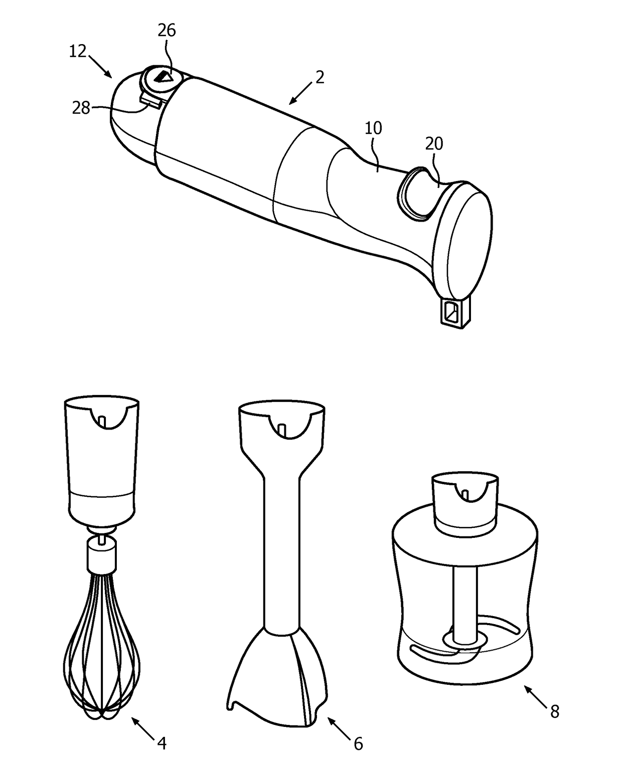
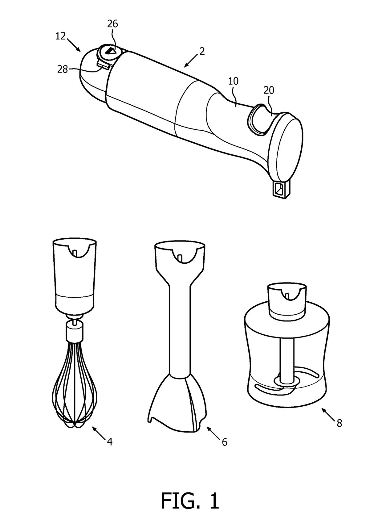
[0045]Referring to FIGS. 1 and 2, a power unit 2 provides power for one of a number of tools 4, 6, 8. In the example, the power unit 2 is a power unit of a hand blender. The tools include a blender attachment 4, a whisk attachment 6 and a food processor attachment 8, the latter including a bowl, a blade and adapter to allow the power unit 2 to rotate the blade in the bowl to process food.

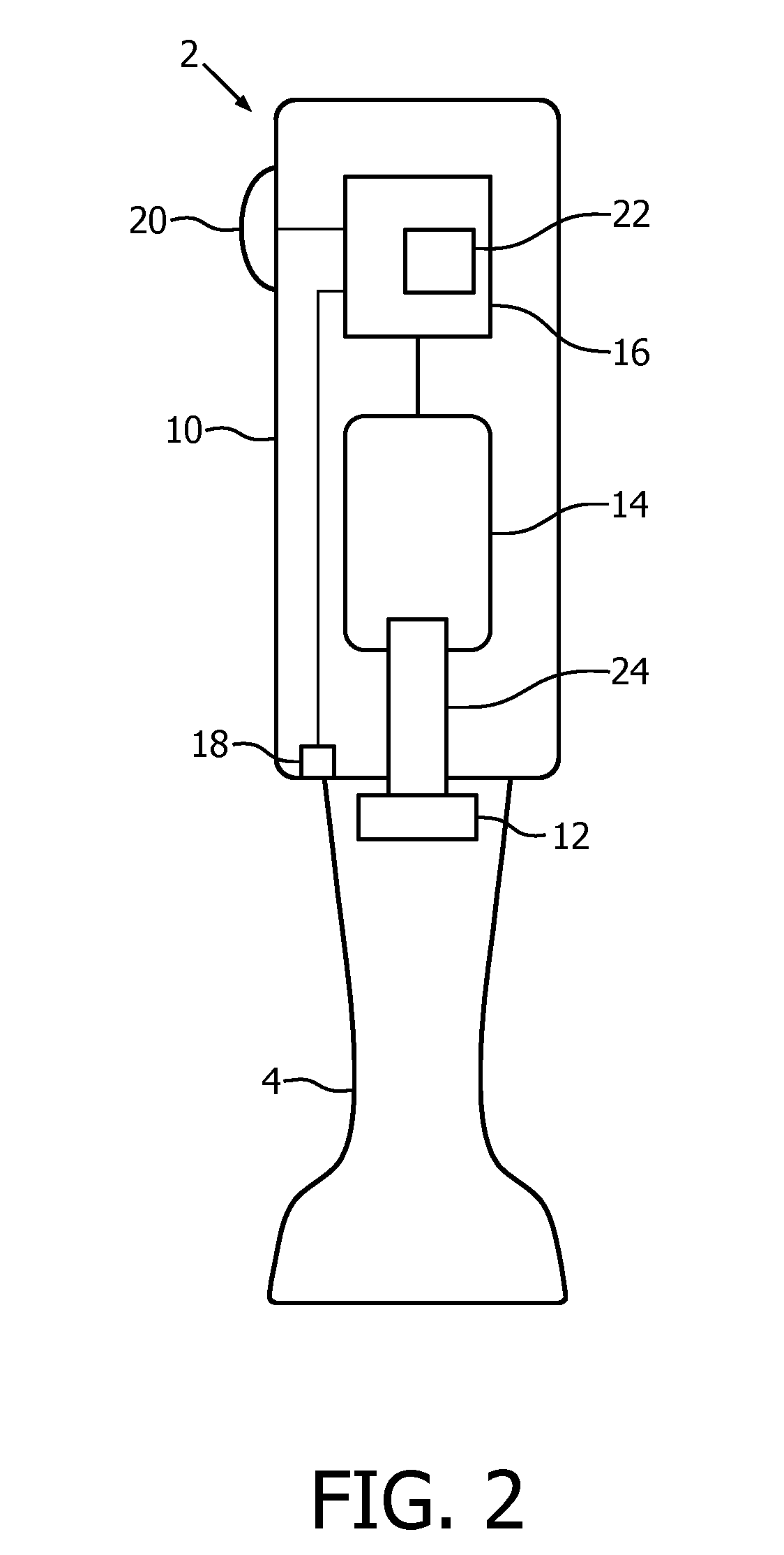
[0046]The power unit 2 has a housing 10 and includes a coupling 12 which is a mechanical interface for coupling a rotary drive to one of the tools. Tools 4, 6, 8 may be attached in a releasable manner so that the tools may be attached and detached from the power unit 2. In the example, external detent tangs 28 are used to clip the a tool 4, 6, 8 to the power unit 2 and the tool may be released by operating release switch 26 which retracts detent tang 28 releasing the tool.

[0047]An electric motor 14 is provided which is mechanical...


PUM


Abstract

A kitchen appliance has a power unit 2 and a removable tool 4 connected through a mechanical interface 12. A controller 16 controls an electric motor 14 driving the tool 4 through the mechanical interface. A vibration sensor 18 identifies the vibrations of the tool and feeds the vibration data to the controller 16. The controller may use the vibration data to identify the tool and/or to select an appropriate drive pattern based on the sensed vibration.

Description

FIELD OF THE INVENTION[0001]The invention relates to kitchen appliances and in particular to kitchen appliances with exchangable tools.BACKGROUND OF THE INVENTION[0002]Electrically powered kitchen appliances are becoming increasingly popular around the world. Such kitchen appliances include hand blenders, blenders, food processors, bread makers and mixers, typically including one or more accessories driven by an electric motor. To meet a variety of needs, appliances are being designed with an increasing number of applications and functions.[0003]In some kitchen appliances, the variety of functions may be included in a single integrated device. In such appliances, it is easy to control the different functions and to adjust the motor power and speed for each function, since the user adjusts a control to select the required function and that control can both select the required function and also select suitable motor drive parameters such as motor speed which in turn influences motor t...

Claims


Application Information

Patent Timeline
IPC IPC(8): A47J43/06A47J43/08A47J43/07A47J43/28
CPCA47J43/06A47J43/082A47J43/0711A47J43/288A47J2043/04418
Inventor WEISS, SASCHASIGOT, THOMAS LEONHARD
Owner KONINKLJIJKE PHILIPS NV
Why Eureka
Try Eureka