
Vehicle gauge with embedded driver information

a technology of driver information and vehicle gauge, which is applied in the field of vehicle instrumentation, can solve the problems of affecting styling or functionality, affecting the appearance of vehicles, and reducing the service life of vehicles,

Inactive Publication Date: 2008-03-25
YAZAKI NORTH AMERICA
View PDF50 Cites 11 Cited by
  • Summary
  • Abstract
  • Description
  • Claims
  • Application Information

AI Technical Summary

Benefits of technology

The present invention provides a gauge with a pointer and a display that can be easily viewed through the pointer. The pointer is movable and can be illuminated by a light source to provide visibility. The display can be a liquid crystal display, OLED display, or a thin film electroluminescent display. The motor assembly can rotate the pointer, and the light source can illuminate at least the pointer. The technical effects of the invention include improved visibility and ease of use for measuring and monitoring purposes.

Problems solved by technology

More specifically, this area can at times be rather inefficiently or ineffectively utilized and thereby detract from styling or functionality.
Construction of the analog vehicle gauge in this manner, however, necessitates reconfiguration of the pointer and potentially the drive system for the movement of the pointer.
The pointer, however, has a relatively complex shape that is more costly to produce, can be difficult to backlight and has a relatively large mass.
Since the torque of a motor and its size tend to be directly related, and since larger motors are typically more costly and difficult to package within an instrument cluster, pointers having a relatively large mass can be less desirable in many situations.
The flexible circuit adds complexity and cost to the analog vehicle gauge as well as reduces reliability.

Method used


Image

  • Vehicle gauge with embedded driver information
  • Vehicle gauge with embedded driver information
  • Vehicle gauge with embedded driver information

Examples


Embodiment Construction

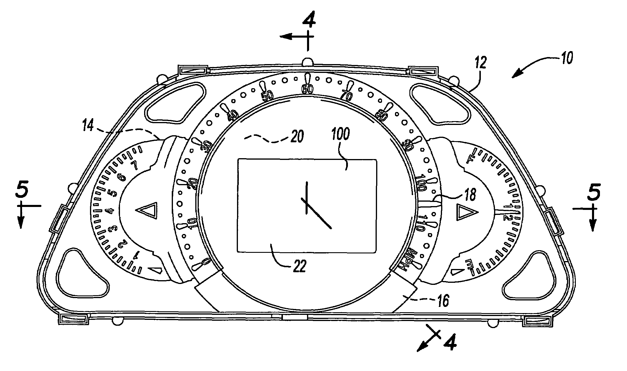
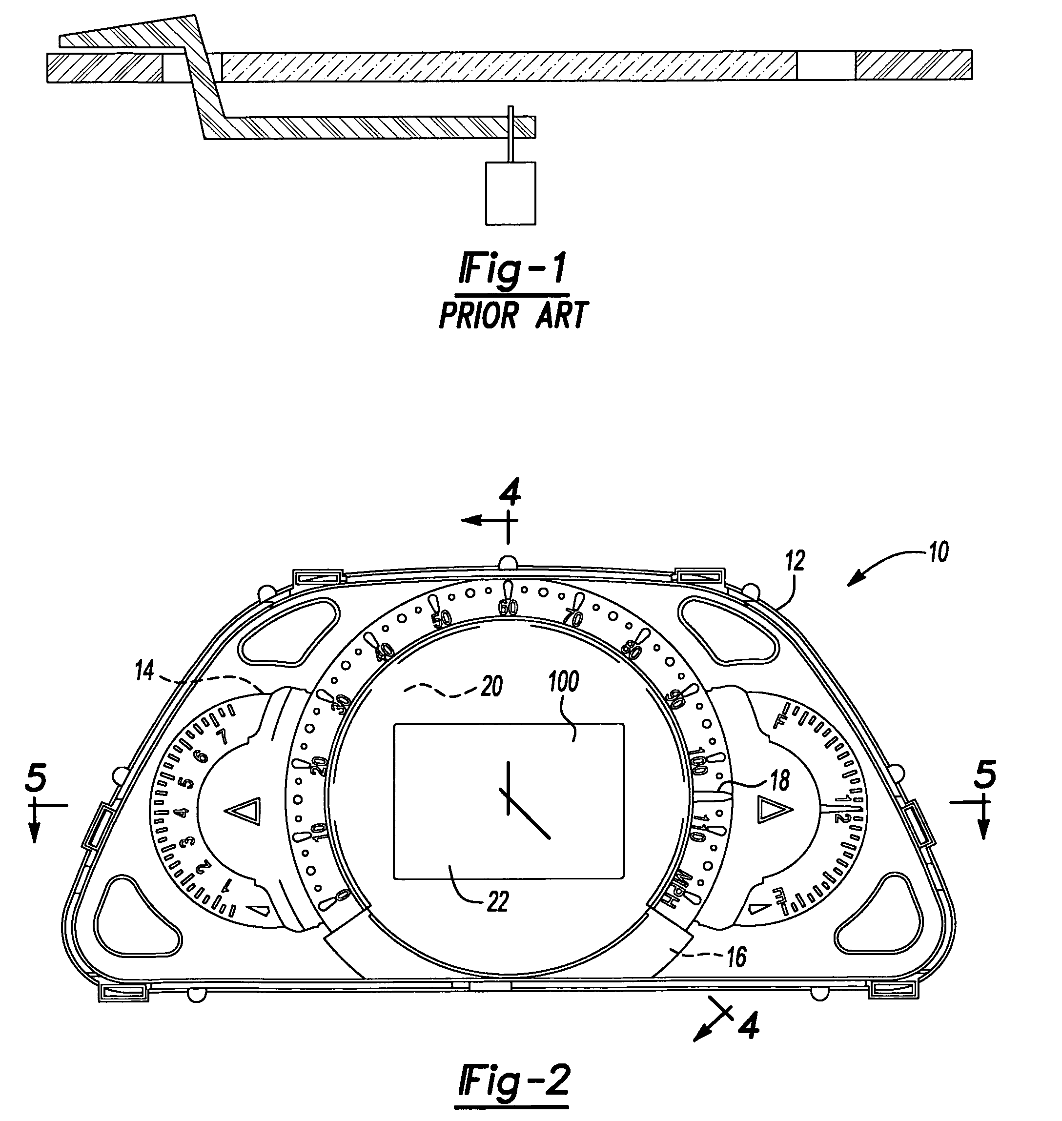
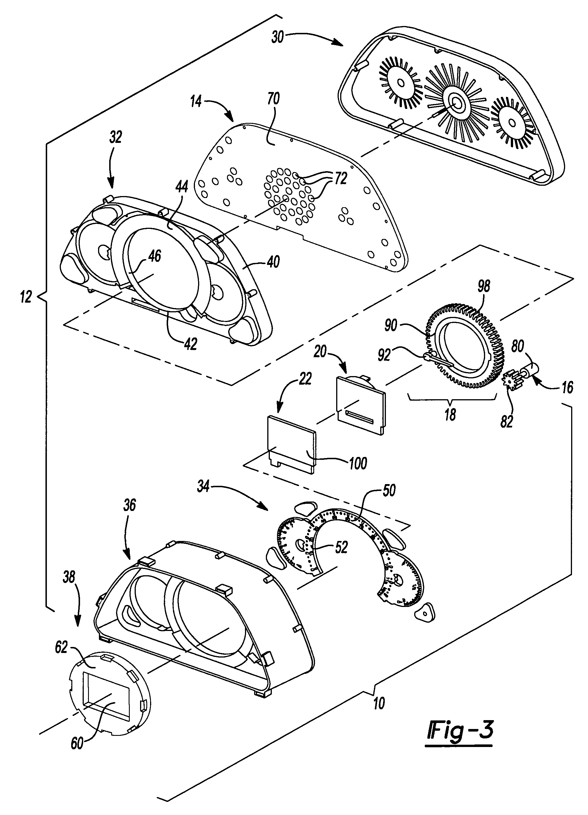
[0019]With reference to FIGS. 2 through 4 of the drawings, an analog vehicle gauge constructed in accordance with the teachings of the present invention is generally indicated by reference numeral 10. The gauge 10 can include a housing 12, a circuit board assembly 14, a motor assembly 16, a pointer 18, a light guide 20 and a display 22.

[0020]The housing 12 can include a rear housing 30, a reflector housing 32, an appliqué34, a front mask 36 and a bezel 38. The rear housing 30 can cooperate with the reflector housing 32 to define a cavity in which the circuit board assembly 14 may be housed.

[0021]The reflector housing 32 can have housing body 40, which can include a sleeve 42 and a reflector member 44 that can extend about a portion of the sleeve 42. The sleeve 42 can be tubular structure that extends forwardly from an adjacent portion of the housing body 40. A plurality of windows 46 can be formed through the sleeve 42 to interconnect the space that is bounded by the reflector membe...


PUM


Abstract

A gauge having a housing, a light source disposed in the housing, a bezel, a display and a pointer. The display is coupled to the housing and includes a display surface that is visible through an opening in the bezel. The display is spaced rearwardly of the bezel to define a light transmitting aperture. The pointer is movably mounted to the housing and includes a pointer end that is disposed on a side of the bezel opposite the light transmitting aperture. A first portion of the light produced by the light source can be employed to back-illuminate the display surface, while a second portion of the light produced by the light source can be collected by the pointer and employed to illuminate the pointer end.

Description

CROSS-REFERENCE TO RELATED APPLICATIONS[0001]This application claims the benefit of U.S. Provisional Patent Application Ser. No. 60 / 587,539 entitled “Vehicle Gauge With Embedded Driver Information” filed Jul. 13, 2004.INTRODUCTION[0002]The present invention generally relates to vehicle instrumentation and more particularly to an analog vehicle gauge with a rotary pointer and a central display.[0003]Traditionally, analog vehicle gauges have employed an arrangement of light guides, reflectors and light bulbs or LEDs. These traditional analog gauges typically employ a moveable pointer that is rotatably coupled to the output shaft of a motor, such as a stepper motor or an aircore movement. One characteristic of this traditional arrangement concerns the area located inwardly of the gauge's scale or indicia. More specifically, this area can at times be rather inefficiently or ineffectively utilized and thereby detract from styling or functionality.[0004]One proposal that we have considere...

Claims


Application Information

Patent Timeline
Patent Type & Authority Patents(United States)
IPC IPC(8): G01D11/28B60Q3/04
CPCB60K37/02G01D7/002G01D11/28G01D13/265B60K2350/203B60K35/60B60K2360/33B60K2360/6992B60K2360/6985
Inventor FONG, CHINGVENKATRAM, SANJIVKELMAN, ZINOVIYPASEK, JOSEPHDEMHLOW, BRIAN P
Owner YAZAKI NORTH AMERICA
Learn More