Vehicle control apparatus

Active Publication Date: 2018-06-21
TOYOTA JIDOSHA KK
View PDF0 Cites 9 Cited by
  • Summary
  • Abstract
  • Description
  • Claims
  • Application Information

AI Technical Summary

Benefits of technology

[0017]In the control apparatus according to the fourth mode of the invention, when the maximum charging amount of the electric power storage device is limited and the fuel cut of the engine is not executed during the power-off shift-up action of the step-variable transmission, the torque capacity of the step-variable transmission is generated or increased thereby causing a drag in the step-variable transmission, so that an inertia energy is consumed by the drag caused in the step-variable transmission thereby making it possible to cause the shifting action to progress.
[0018]In the control apparatus according to the fifth mode of the invention, when the maximum discharging amount of the electric power storage device is limited and the fuel cut of the engine is executed during the power-off shift-up action of the step-variable transmission, the target trajectory of the rotational acceleration value of the second motor/generator is shifted toward a negative side as compared with when the maximum discharging amount is not limited, such that the rotating speed of the engine is changed substantially in the same manner as when the maximum discharging amount is not limited. Thus, the progress of the shifting action can be accelerated whereby an excessive reduction of the rotating speed of the engine can be restrained.
[0019]In the control apparatus according to the sixth mode of the invention, when the maximum charging amount of the electric power storage device is limited during the power-off shift-dow

Problems solved by technology

However, it is difficult to precisely know or grasp a target trajectory that is to be followed by each of the target value during the shifting action of the s

Method used


Image

  • Vehicle control apparatus
  • Vehicle control apparatus
  • Vehicle control apparatus

Examples


embodiment

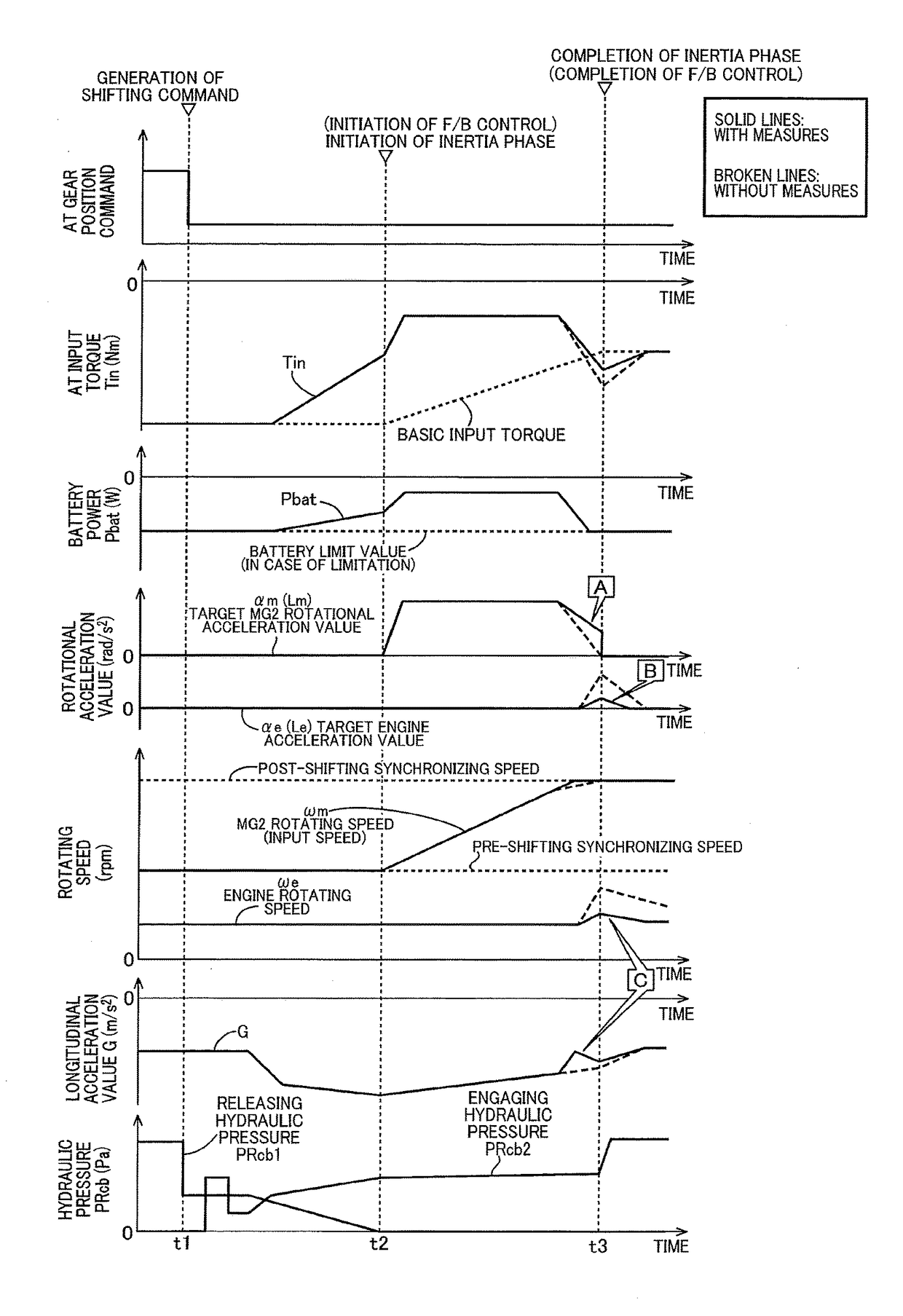
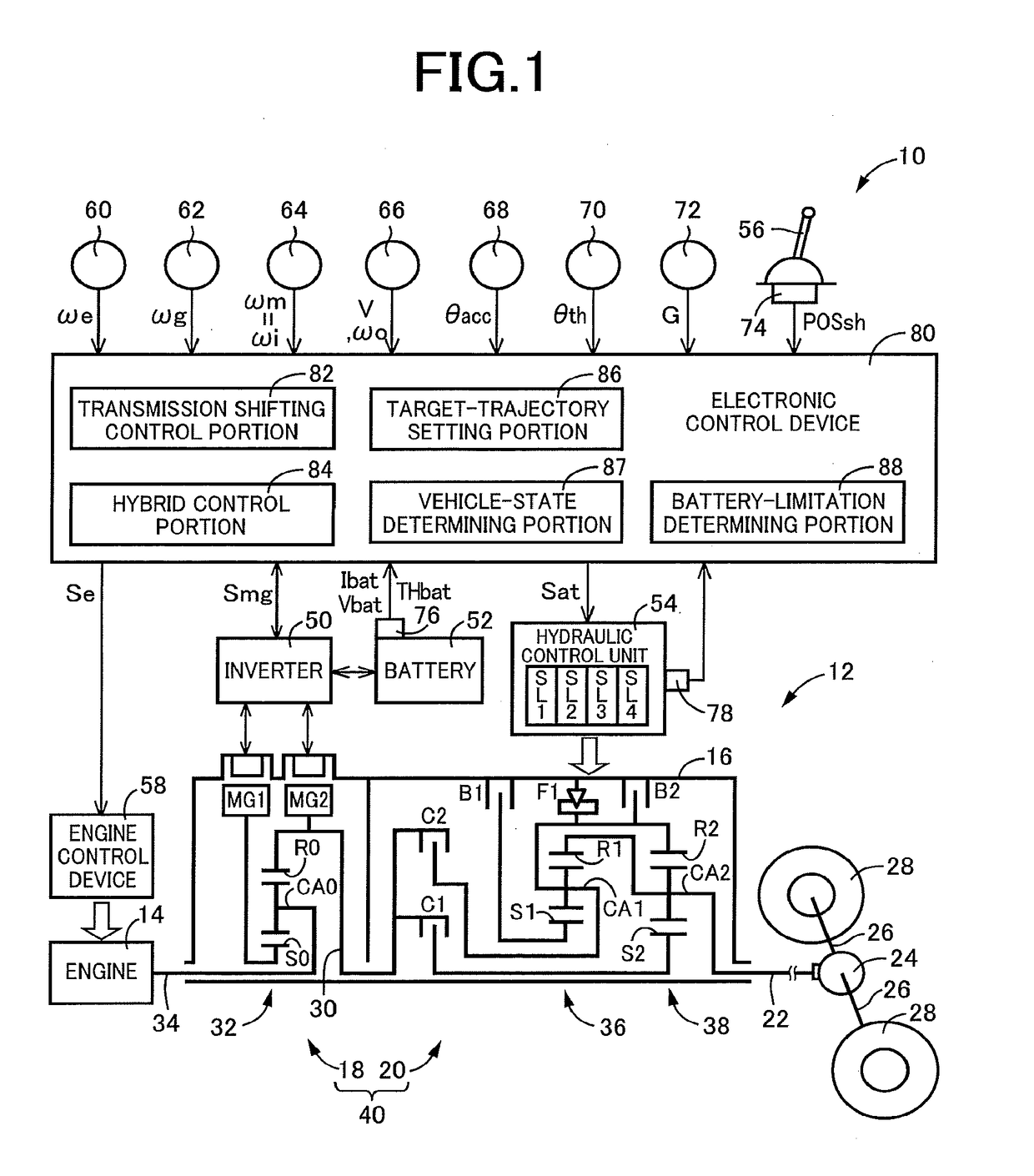
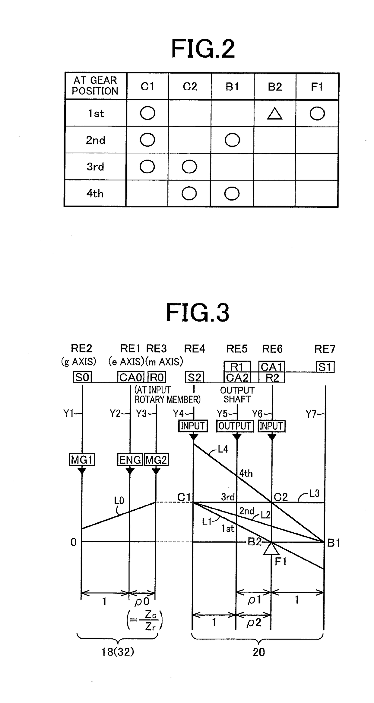
[0035]Reference is first made to FIG. 1, which is the schematic view showing an arrangement of a drive system 12 of a vehicle 10 to be controlled by a control apparatus according to the present invention, and major portions of the control apparatus to perform various controls of the vehicle 10. As shown in FIG. 1, the vehicular drive system 12 is provided with an engine 14, an electrically controlled continuously variable transmission portion 18 (hereinafter referred to as “continuously variable transmission portion 18”) connected directly or indirectly via a damper (not shown) or any other device to the engine 14, and a mechanically operated step-variable transmission portion 20 (hereinafter referred to as “step-variable transmission portion 20) connected to an output rotary member of the continuously variable transmission portion 18. The continuously variable transmission portion 18 and the step-variable transmission portion 20 are disposed in series with each other within a trans...


PUM


Abstract

A vehicle control apparatus includes: a transmission shifting control portion configured to implement a shifting action of a step-variable transmission by controlling a releasing coupling device and an engaging coupling device; a hybrid control portion configured to control an output torque of a first motor/generator and an output torque of a second motor/generator, based on an output torque of an engine and a transmitted torque to be transmitted through an initiative coupling device, such that a rotational acceleration value of the second motor/generator and a rotational acceleration value of the engine are changed along respective target trajectories during the shifting action; and a target-trajectory setting portion configured to set the target trajectories, based on a maximum charging amount of an electric power that is chargeable to an electric power storage device and a maximum discharging amount of the electric power that is dischargeable from the electric power storage device.

Description

[0001]This application claims priority from Japanese Patent Application No. 2016-247202 filed on Dec. 20, 2016, the disclosure of which is herein incorporated by reference in its entirety.FIELD OF THE INVENTION[0002]The present invention relates to a control apparatus for a hybrid vehicle provided with a differential mechanism and a step-variable transmission that are disposed in series.BACKGROUND OF THE INVENTION[0003]There is well known a control apparatus for a hybrid vehicle provided with (i) an engine; (ii) a first motor / generator; (iii) a second motor / generator which is operatively connected to an intermediate power transmitting member; (iv) a differential mechanism having three rotary elements to which the engine, first motor / generator and intermediate power transmitting member are respectively connected; (v) a step-variable transmission which constitutes a part of a power transmitting path between the intermediate power transmitting member and drive wheels and which is place...

Claims


Application Information

Patent Timeline
IPC IPC(8): B60K6/365B60K6/445B60W30/19B60W10/10B60L50/16
CPCB60K6/365B60K6/445B60W30/19B60W10/10B60W2510/244B60W2710/0661B60W2710/082B60W2710/083B60W10/06B60W10/11B60W10/12B60W20/00B60W20/30B60K6/547B60W10/08B60W10/115B60W10/26B60W2710/248Y02T10/62Y02T10/72
Inventor SUGIYAMA, KOJIKUMAZAKI, KENTAKIMURA, HIROMICHISHIIBA, KAZUYUKIMATSUBARA, TOORUSASADE, SHINICHIKITAHATA, TAKESHIKOBAYASHI, NOBUFUSAYOSHIKAWA, MASATO
Owner TOYOTA JIDOSHA KK
Why Eureka
Try Eureka