Idle speed control apparatus and method for internal combustion engine

a control apparatus and internal combustion engine technology, applied in the direction of electric control, ignition automatic control, machines/engines, etc., can solve the problems of insufficient increase of exhaust gas temperature, inability to activate catalysts, and inability to increase the total amount of exhaust gas emitted from vehicles, so as to increase the temperature of the catalytic device, increase the effect of exhaust gas temperature and high responsiveness

Inactive Publication Date: 2005-06-07
MITSUBISHI MOTORS CORP
View PDF6 Cites 7 Cited by
  • Summary
  • Abstract
  • Description
  • Claims
  • Application Information

AI Technical Summary

Benefits of technology

[0016]With the above arrangement, when the engine is started in the cold mode, the ignition timing is retarded and the engine speed of the engine is feedback-controlled to the target engine speed. As a result, it is possible to promptly increase the exhaust gas temperature and increase the temperature of the catalytic device, and to control the engine speed to the target engine speed with a high responsiveness and to inhibit a surge in the engine speed, thus suppressing the emission of unburned fuel at the time of cold-start. Thereafter, the intake air quantity is controlled to feed-back control the engine speed to the target engine speed, so that the idle speed can be stabilized while the catalyst temperature is increased in an efficient manner by retarding the ignition timing.

Problems solved by technology

Incidentally, in the case of an electronically controlled throttle valve used in an idle speed control apparatus for an internal combustion engine, the intake air quantity Qa is likely to deviate due to aging changes of the throttle valve or variations among products.
In this case, the advancement of the target ignition timing IGT has a deficiency equivalent to the deviation ΔIGT, and this leads to insufficient increase of the exhaust gas temperature.
As a result, the activation of a catalyst is delayed to increase the total amount of exhaust gases emitted from a vehicle.

Method used


Image

  • Idle speed control apparatus and method for internal combustion engine
  • Idle speed control apparatus and method for internal combustion engine
  • Idle speed control apparatus and method for internal combustion engine

Examples


Embodiment Construction

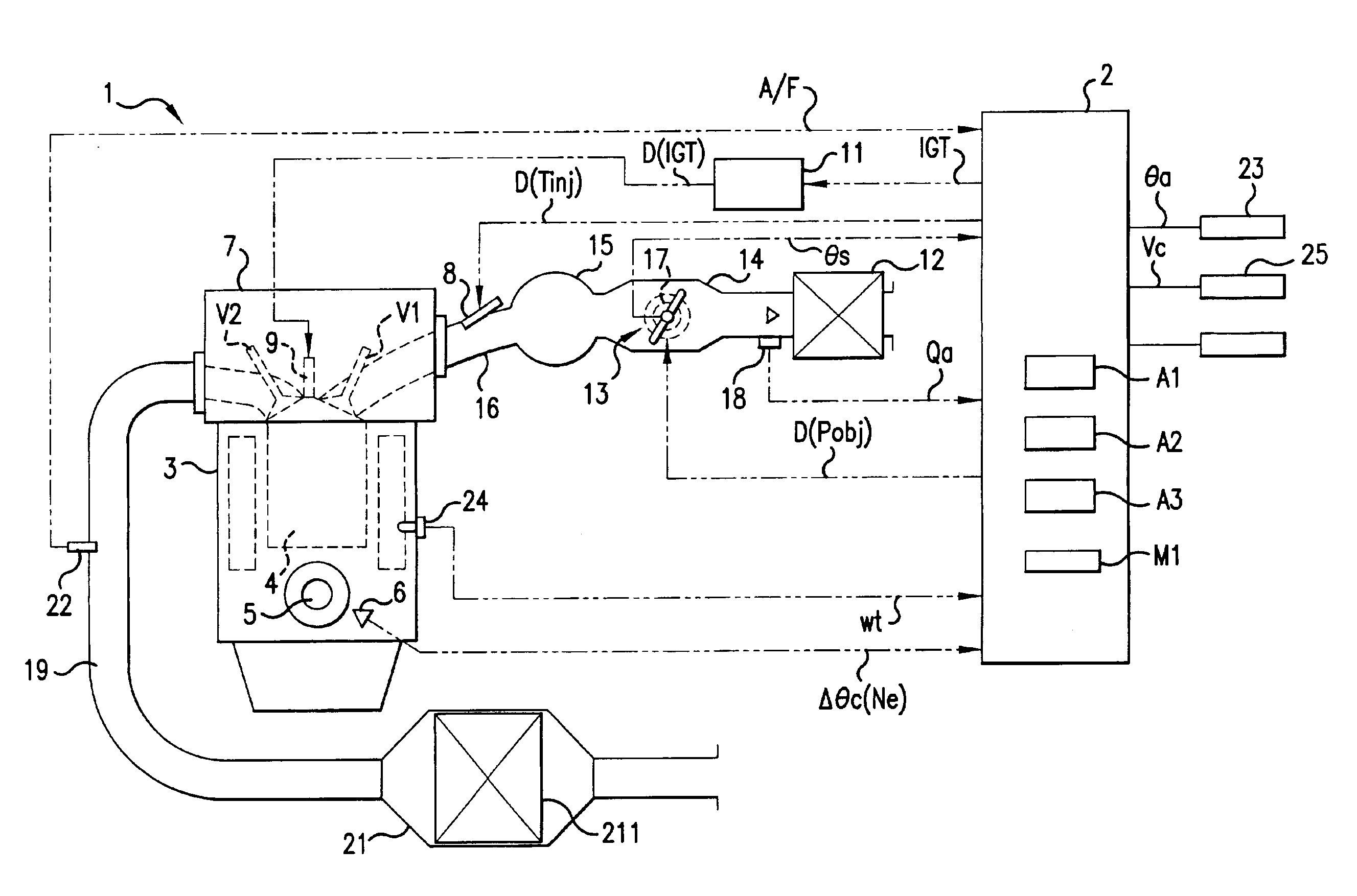
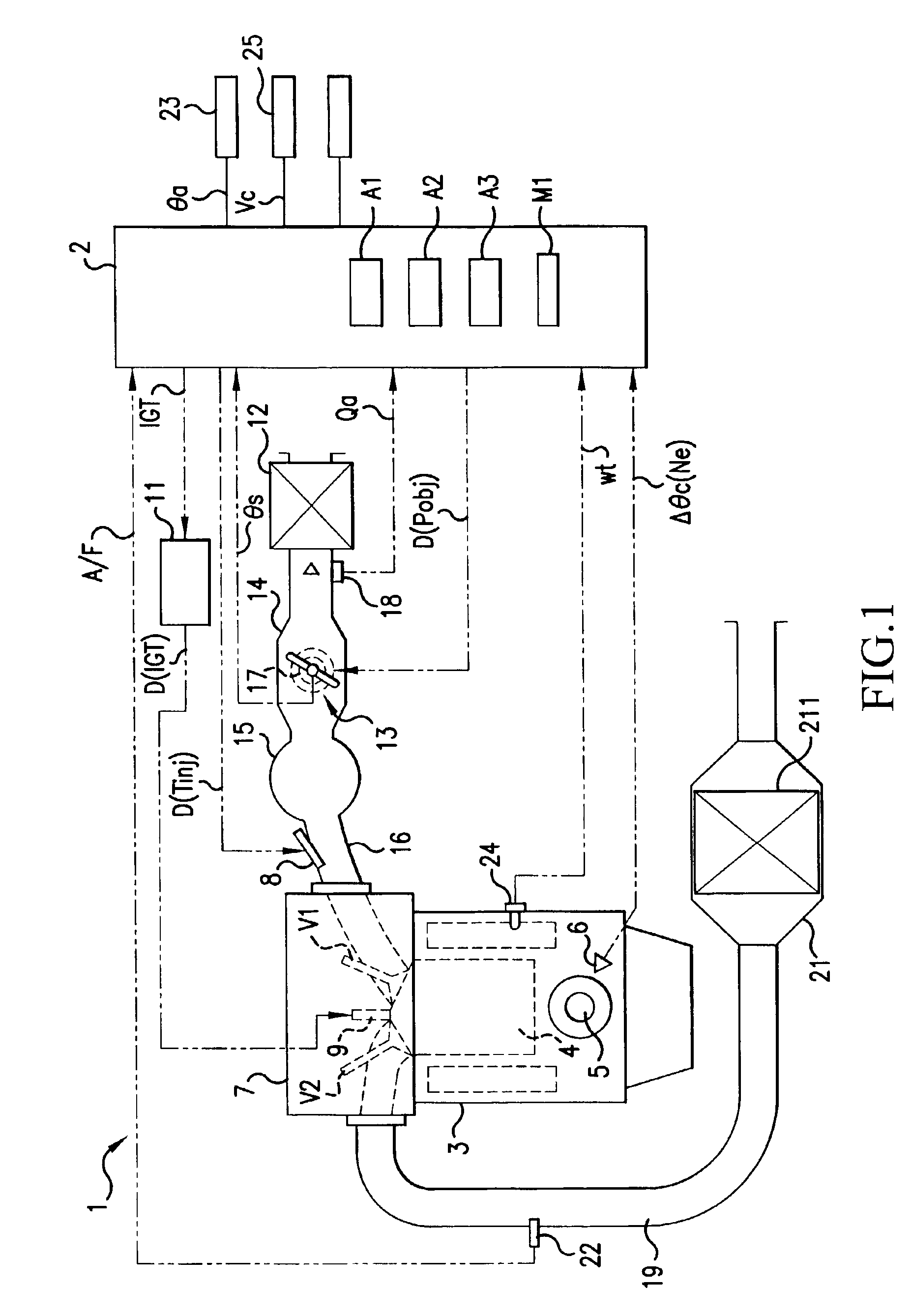
[0032]The present invention will now be described in further detail with reference to the drawings showing an embodiment thereof. FIG. 1 illustrates an idle speed control apparatus for an internal combustion engine, and an engine 1 as the internal combustion engine equipped with the idle speed control apparatus. The engine 1 in FIG. 1 is used to produce power for driving a vehicle, and a controller 2 controls an intake system, fuel supply system, and ignition system of the engine 1.

[0033]The engine 1 is provided with a plurality of combustion chambers 4 (only one is illustrated in FIG. 1) arranged in a cylinder block 3. The action of a piston, not shown, provided in each of the combustion chambers 4 is converted into torque by a crank shaft 5, and is transmitted to a rotation driving system, not shown. A crank angle sensor 6 is opposed to the crank shaft 5, and outputs crank angle information Δηc to the controller 2. The controller 2 derives the engine speed Ne from the crank angle ...


PUM


Abstract

An idle speed control apparatus for an internal combustion engine is provided which, when the internal combustion engine is started in a cold mode, provides ignition timing engine speed control (m1) such that ignition timing in which said ignition driving device performs ignition in the internal combustion engine is retarded and the engine speed of the internal combustion engine is controlled to the target engine speed, and then provides intake air quantity engine speed control (m2) such that the engine speed of the internal combustion engine is feedback-controlled to the target engine speed by controlling the intake air quantity of the internal combustion engine. As a result, it is possible to prevent the exhaust gas temperature from being increased insufficiently due to a deficiency in retard angle, and to prevent the activation of a catalytic converter from being delayed.

Description

CROSS-REFERENCE TO RELATED APPLICATIONS[0001]This application incorporates by reference the subject matter of Application No. 2002-101470 filed in Japan on Apr. 3, 2002, on which a priority claim is based on under 35 U.S.C. §119(a).BACKGROUND OF THE INVENTION[0002](1) Field of the Invention[0003]The present invention relates to an idle speed control apparatus that controls an idle speed of an internal combustion engine according to an operating state of the engine. In particular, the present invention relates to an idle speed control apparatus that controls an idle speed of an internal combustion engine according to an ignition timing controlled for promoting the warm-up.[0004](2) Description of the Related Art[0005]An internal combustion engine is required to stabilize its idling operation when it is cold started. The internal combustion engine is also required to promote the warm-up so as to promptly activate a catalyst and ensure desired exhaust gas purifying performance.[0006]Th...

Claims


Application Information

Patent Timeline
Patent Type & Authority Patents(United States)
IPC IPC(8): F02D37/00F02D41/08F02D37/02F02D41/06F02P5/15F02D41/02F02D41/00F02D41/16F02D43/00F02D45/00
CPCF02D37/02F02D41/068F02D41/08F02P5/1508F02D41/064F02D41/0002F02D41/0255Y02T10/46Y02T10/40
Inventor MIYAMOTO, KATSUHIKONAKAI, HIDEOMAEDA, KATSUYUKISHIOTA, SEIJI
Owner MITSUBISHI MOTORS CORP
Why Eureka
Try Eureka