Internal combustion engine

Active Publication Date: 2018-06-21
DEUTZ AG
View PDF24 Cites 0 Cited by
  • Summary
  • Abstract
  • Description
  • Claims
  • Application Information

AI Technical Summary

Benefits of technology

The patent describes a way to optimize the engine in a vehicle by integrating a cooling circuit for the engine control unit and intercooler system. This allows for better engine performance and better fuel efficiency. The intercooler can also be switched off at cold temperatures. Overall, this patent aims to improve the performance of the vehicle's engine through advanced design features.

Problems solved by technology

At the present time, achieving a highly efficient oil separation poses huge problems for the crankcase ventilation system.
The technical resources involved for this are considerable and correspondingly costly.

Method used


Image

  • Internal combustion engine
  • Internal combustion engine
  • Internal combustion engine

Examples


Embodiment Construction

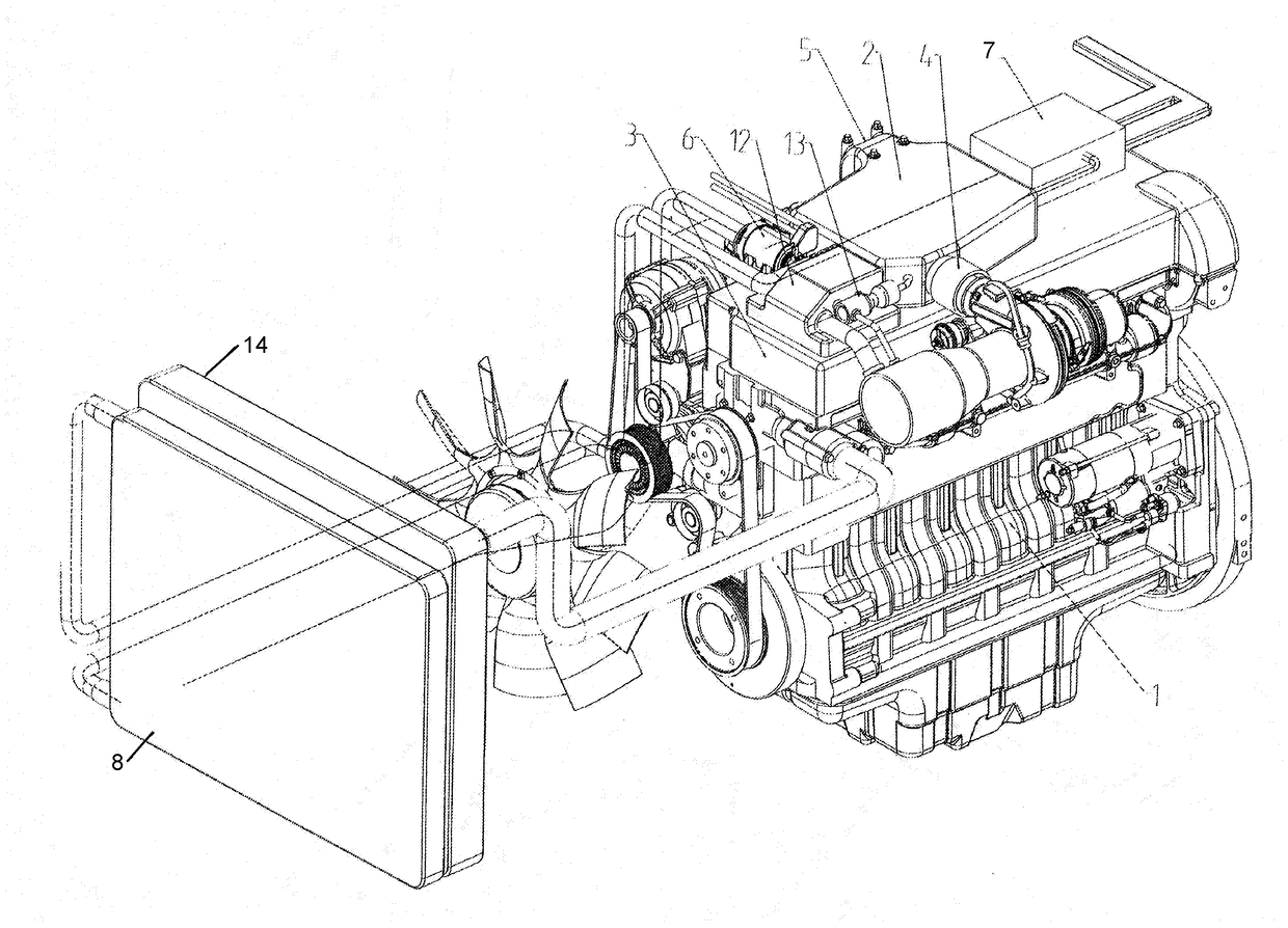
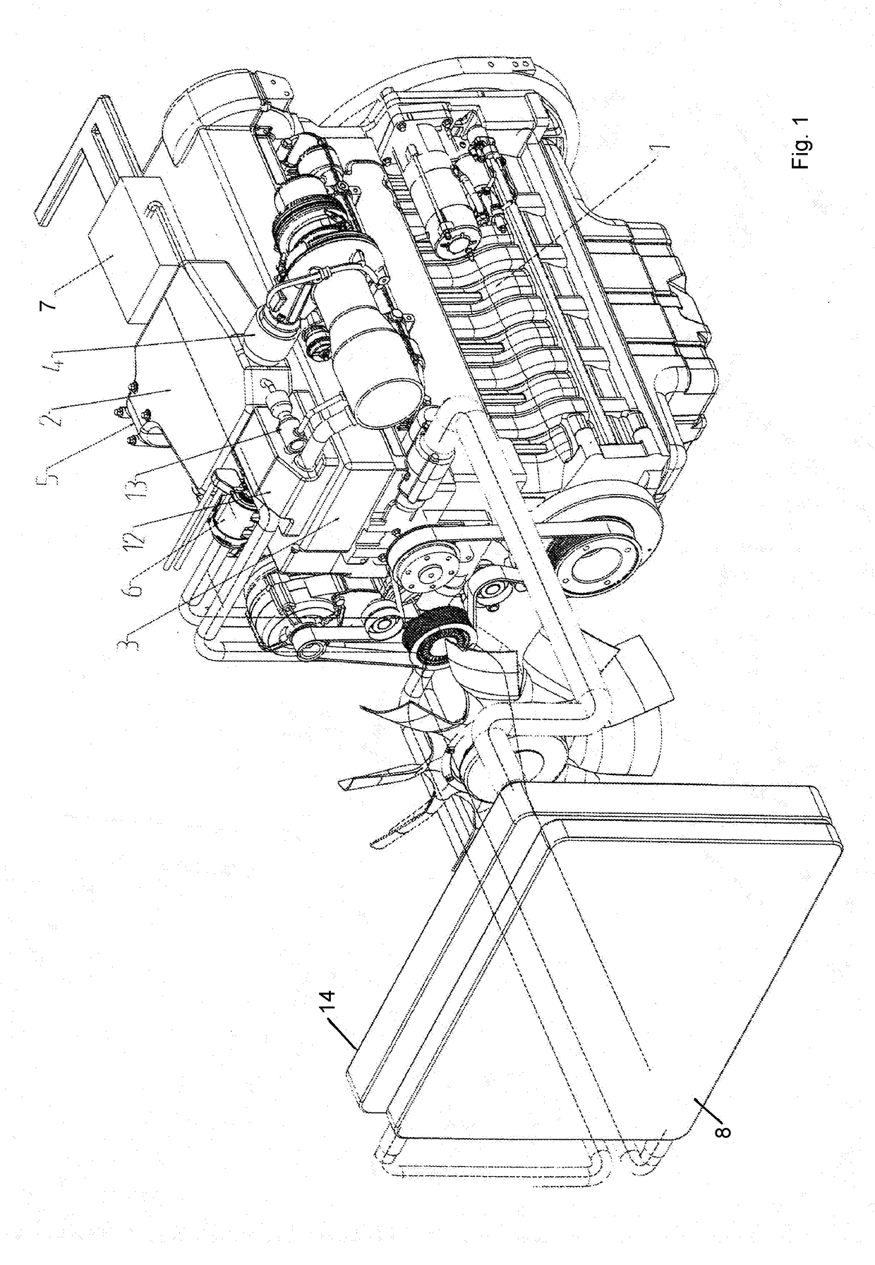
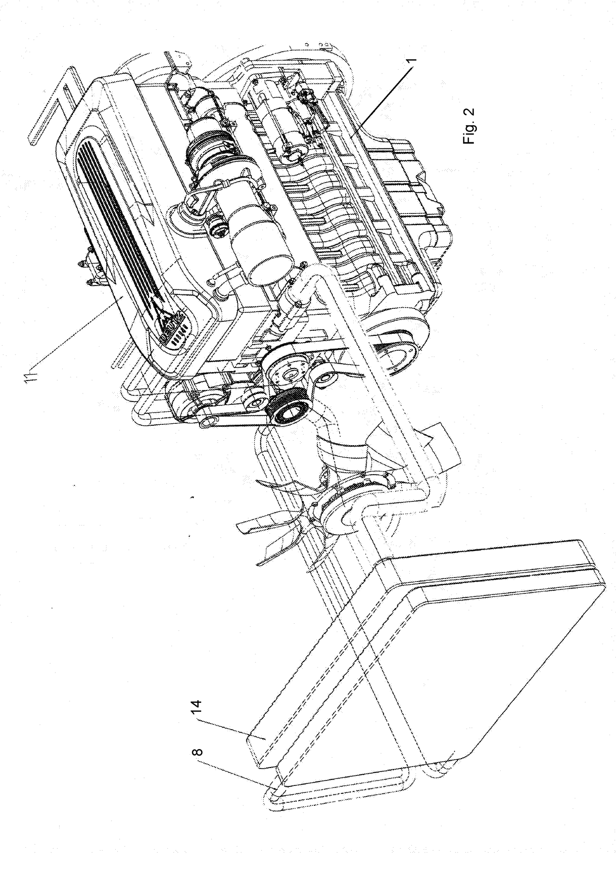
[0028]FIG. 1 shows a view of an internal combustion engine 1 having a high-temperature and a low-temperature circuit without a hood 11, which will be visible in the figures that follow.

[0029]The reciprocating engine 1 has a low-temperature water-air intercooler 2 that is arranged on its valve cover hood 3 in such a way that the uncooled air from the turbocharger 4 can enter the low-temperature water-air intercooler 2 directly, without the need for additional piping. The cold charge air leaving the low-temperature water-air intercooler 2 upstream from the inlet valves of the engine 5 likewise only requires minimum resources in terms of piping. The coolant pump 6, which is located close to the intercooler, ensures an efficient throughput of the coolant in the low-temperature water circuit and, upon request by the engine control unit 7, it pumps the water through the low-temperature cooler 8. The crankcase ventilation system 12 arranged above the valve cover hood 3 is directly adjacent...


PUM


Abstract

An internal combustion engine, especially a diesel internal combustion engine, having at least one intercooler, at least one control unit, at least a first and a second cooling circuit, whereby the cooler of the first cooling circuit is flow-connected to a cooling circuit of the internal combustion engine, while the cooler of the second cooling circuit of the internal combustion engine is flow-connected to the intercooler.

Description

[0001]This claims the benefit of German Patent Application DE 10 2016 014 904.3, filed Dec. 6, 2016 and hereby incorporated by reference herein.[0002]The invention relates to an internal combustion engine, especially a diesel internal combustion engine, having at least one intercooler, at least one control unit, at least a first and a second cooling circuit, whereby the cooler of the first cooling circuit is flow-connected to the cooling means of the internal combustion engine, while the cooler of the second cooling circuit of the internal combustion engine is flow-connected to the intercooler.BACKGROUND[0003]German patent application DE 10 2004 047 452 A1 discloses a cooling system for an internal combustion engine, comprising a first cooling circuit for a cylinder head and a second cooling circuit for an engine block, which are connected to each other. A controllable setting member is situated between the first and second cooling circuits in order to regulate the distribution of a...

Claims


Application Information

Patent Timeline
IPC IPC(8): F02B29/04F01P7/16F01P3/04
CPCF02B29/0443F01P7/165F01P3/04F01P7/162F01P7/164F01P2060/02F01P2005/125F01M13/00F01M13/04F01P3/20F02B29/0437F02B77/13F02F7/0065F02F7/007F02F7/008F02M35/10222F02B29/0406F02B29/0412F02M25/06F02B77/11F02F7/006Y02T10/12
Inventor JOISTEN-PIERITZ, JOACHIMSCHWABAUER, PAUL
Owner DEUTZ AG
Why Eureka
Try Eureka