Supercharge Your Innovation With Domain-Expert AI Agents!

Cooling tower wind wall system

a cooling tower and wind wall technology, applied in the direction of trickle coolers, lighting and heating apparatus, separation processes, etc., can solve the problems of preventing airflow into the cooling tower, affecting the safety of users, etc., to slow down the wind, and reduce the effect of wind velocity

Active Publication Date: 2018-06-21
BALTIMORE AIRCOIL CO INC
View PDF0 Cites 4 Cited by
  • Summary
  • Abstract
  • Description
  • Claims
  • Application Information

AI Technical Summary

Benefits of technology

The patent text describes a wind wall system to prevent rain water from being blown outside of a cooling tower and to minimize the effect of wind velocity on the water leaving the evaporative heat exchanger. The wind wall system consists of inlet louvers, a top evaporative heat exchanger, a bottom water collection sump, wind walls, and the installation of wind walls from the corners to the middle of the cooling tower. The wind wall system guides the wind perpendicular through the inlet louvers and redirects it towards the wind walls, creating at least four wind zones that slow down and trap the wind. This prevents the water carrying wind from leaving the wind wall zone and ensures the rain zone falling water stays within the cooling tower. The technical effect of this system is to prevent safety and operational issues caused by extreme wind and sub-zero ambient conditions.

Problems solved by technology

Any water that is blown through the inlet louvers and outside of the cooling tower in sub-zero ambient conditions will freeze around the outside of the cooling tower causing safety issues.
In addition, when it is extremely windy and the ambient air temperature is below freezing, any water that is caught and guided by the inlet louvers to the lower basin will freeze and can eventually block all the airflow into the cooling tower.

Method used


Image

  • Cooling tower wind wall system
  • Cooling tower wind wall system
  • Cooling tower wind wall system

Examples


embodiment 21

[0028]Referring now to FIG. 3 of the drawings, embodiment 21 of the present invention is shown which is essentially identical to the embodiment in FIGS. 1 and 2 except the evaporative heat exchanger 25 in an indirect type having internal fluid header connections 24 and 26. Indirect heat exchange section 25 can be seen with gaps which can either be left empty as shown or a direct heat exchange surface may be installed there as known in the art. Whether the evaporative heat exchange section is a direct section only as shown in FIGS. 1 and 2, or an indirect section as shown in FIG. 3, users skilled in the art will recognize that the wind walls system incorporating inlet louvers and wind walls will work no matter what style evaporative heat exchanger is installed.

[0029]Referring now to FIG. 4 of the drawings, embodiment 39 shows more clearly the components of the wind wall system of the prior figures. Lower water collection basin 37 collects rain zone water that rains off of the indirec...

embodiment 50

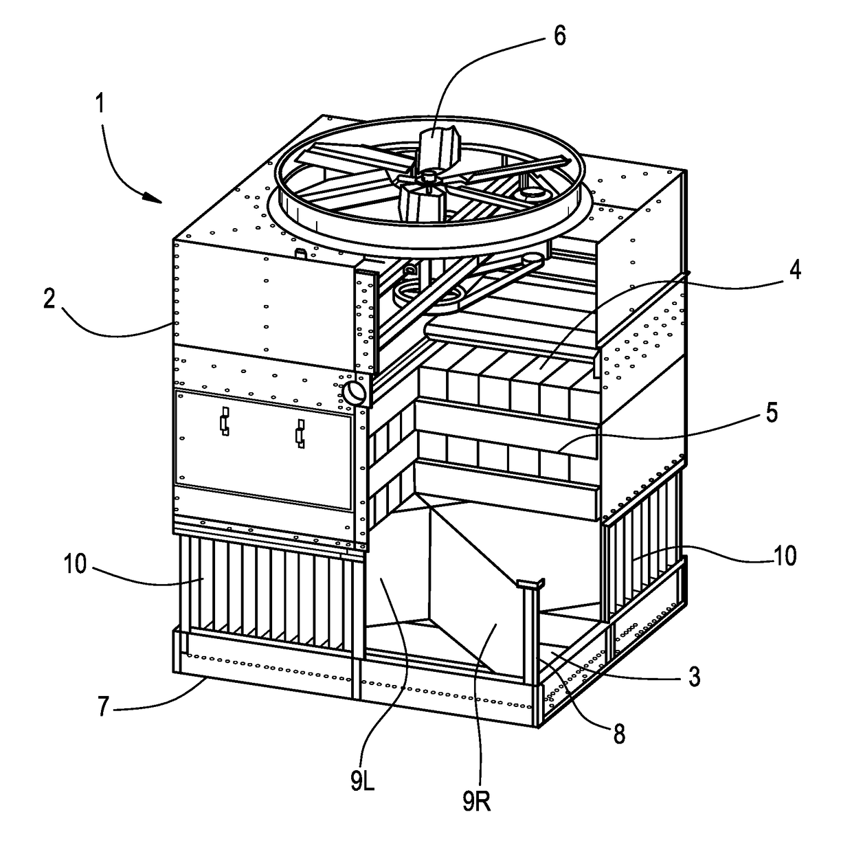
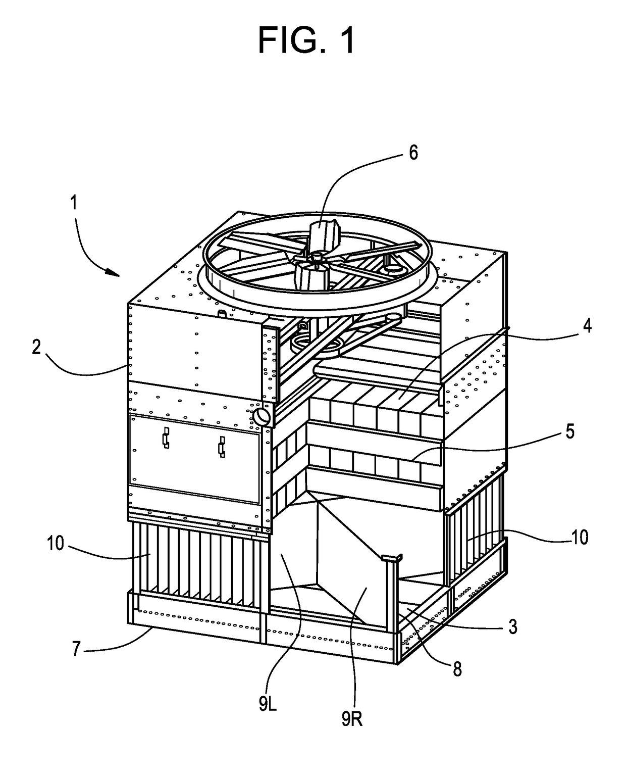
[0030]Referring now to FIG. 5a of the drawings, embodiment 50 is shown with all of the inlet louvers removed for clarity. Wind wall 9L starts from front corner of side 7 and is attached to corner vertical support 31 while wind wall 9R starts from the front right corner of side 7 and is attached to corner vertical support 8. Note that there are essentially two wind walls for each side and that wind wall 9R also becomes the left wind wall for side 51. Wind wall 9R can run continuous from vertical support 8 to the back corner of vertical support57 and if desired supported by channel 56. Wind wall 9L can run continuous from vertical support 31 to the back corner of vertical support 52 and if desired supported by channel 58. Wind walls 9L and 9R may be made of any rigid material such as galvanized sheet metal, stainless steel sheet metal, or any suitable weather resistant flexible material such as canvas or PVC. Some customers may choose to install the wind walls only in the winter time ...

embodiment 70

[0033]Referring now to FIG. 7, embodiment 70 is shown with movable wind walls 73. Accordion style or folding style wind wall 73 is shown being attached to linkage 75 and actuator 76. Upon a call for opening or closing from controller 78 connected by wire or pneumatic line 77, actuator 76 moves linkage in or out to open or close wind wall 73. One example of when the wind wall might be operated would be at a temperature below 40F, the wind walls should be closed but can be reopened above 45F ambient temperature to restore ease of maintenance and full cooling tower operation.

[0034]Referring now to FIG. 8, embodiment 80 is shown with wind walls 85 and 87 which can be folded into or out of place. For wind wall 85, permanent frame members 84 and 86 are attached to vertical corner support 83. Wind wall 85 is shown bent away from frame 84 and 86 where it can be folded back for summer time use or folded closed for winter time use. Referring now to FIG. 9, embodiment 91 is shown with sliding ...


PUM

PropertyMeasurementUnit
temperatureaaaaaaaaaa
velocityaaaaaaaaaa
air velocityaaaaaaaaaa

Abstract

A cooling tower is provided having a heat exchange section, and a fan for moving air through the heat exchange section. A water distribution assembly provides water onto and through the heat exchange section. An air inlet section is provided through which air is drawn into the cooling tower and the heat exchange section. The air inlet section has outside edges and corners. A wall assembly is provided in the air inlet section, with the wall assembly extending from the corners of the air inlet section inwardly. The water passing through the heat exchange section enters the air inlet section, and exits to a sump beneath the air inlet section. The air inlet section is comprised of a structure having outside edges and corners, and the wall assembly is comprised of a plurality of wall panel sections. Each wall panel section has an outer edge at a corner of the air inlet section, and each wall panel section extends inwardly from the corner of the air inlet section.

Description

BACKGROUND OF THE INVENTION[0001]The present invention relates generally to an improved wind wall system used within evaporative heat exchange apparatus such as cooling towers, closed circuit fluid coolers, fluid heaters, condensers, evaporators, air coolers or air heaters.[0002]In an evaporative cooling tower, evaporative liquid from a heat load source is sprayed from the top onto a direct heat exchange surface in what is deemed a rain zone and air is moved through the direct heat exchanger to transfer heat from the water directly to the leaving air stream. During winter operation when the ambient air temperature is below freezing, and especially during severe windy conditions, it is desirable that the water falling in the rain zone from the evaporative heat exchanger and into the water collection sump be kept from blowing out of the cooling tower structure or from freezing on surfaces where the ice will cause operational or safety issues.[0003]This invention deals with an improved...

Claims


Application Information

Patent Timeline
Patent Type & Authority Applications(United States)
IPC IPC(8): F28F25/12B01D1/20F28F19/00
CPCF28F25/12B01D1/20F28F19/006F28F2025/005B01D5/003F28F25/087F28C1/12F28C1/16Y02B30/70
Inventor SHIN, YOON K.RUSSELL, GREGORY ADAMMOST, RYAN J.SINGH, RAVINDRAAARON, DAVID ANDREWMORRISON, FRANK T.
Owner BALTIMORE AIRCOIL CO INC
Features
  • R&D
  • Intellectual Property
  • Life Sciences
  • Materials
  • Tech Scout
  • Unparalleled Data Quality
  • Higher Quality Content
  • 60% Fewer Hallucinations
Learn More