FIBER OPTIC PRESSURE APPARATUS, METHODS, and APPLICATIONS

Inactive Publication Date: 2018-06-21
MULTICORE PHOTONICS INC
View PDF7 Cites 5 Cited by
  • Summary
  • Abstract
  • Description
  • Claims
  • Application Information

AI Technical Summary

Benefits of technology

This patent describes a pressure sensor device that includes multiple pressure chambers and optical sensing elements to measure pressure and temperature simultaneously. The pressure sensor device can use different types of pressure transmitting elements, such as diaphragms, flat-plates, curved shells, fiber Bragg gratings, and multicore fiber sensors. The optical sensing elements can be bonded, printed, molded, or micro-fabricated. The technical effect of this patent is to provide a more accurate and reliable measure of pressure and temperature in high-temperature, extreme RF and EMI fields, and to solve for pressure and temperature simultaneously.

Problems solved by technology

This technique, however, does not take advantage of the increased sensitivity provided by measuring the radial and hoop stress of the diaphragm.

Method used


Image

  • FIBER OPTIC PRESSURE APPARATUS, METHODS, and APPLICATIONS
  • FIBER OPTIC PRESSURE APPARATUS, METHODS, and APPLICATIONS
  • FIBER OPTIC PRESSURE APPARATUS, METHODS, and APPLICATIONS

Examples


Embodiment Construction

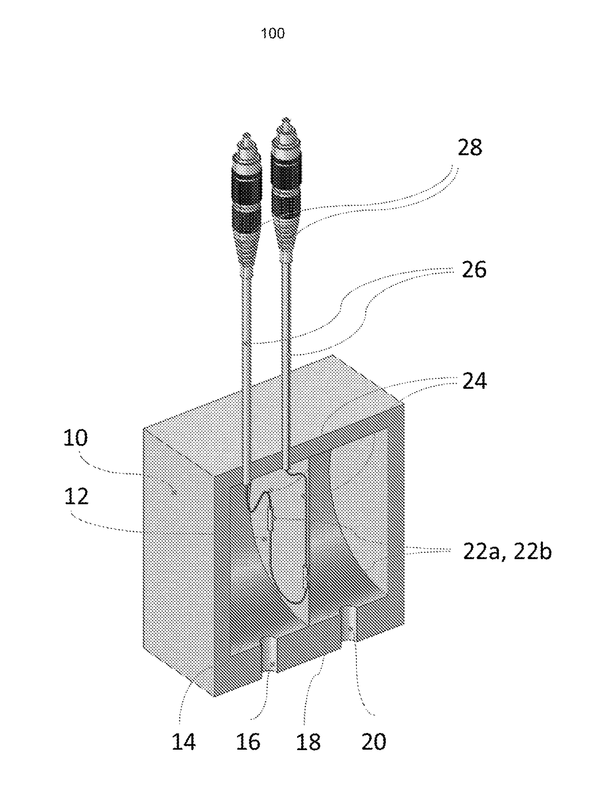
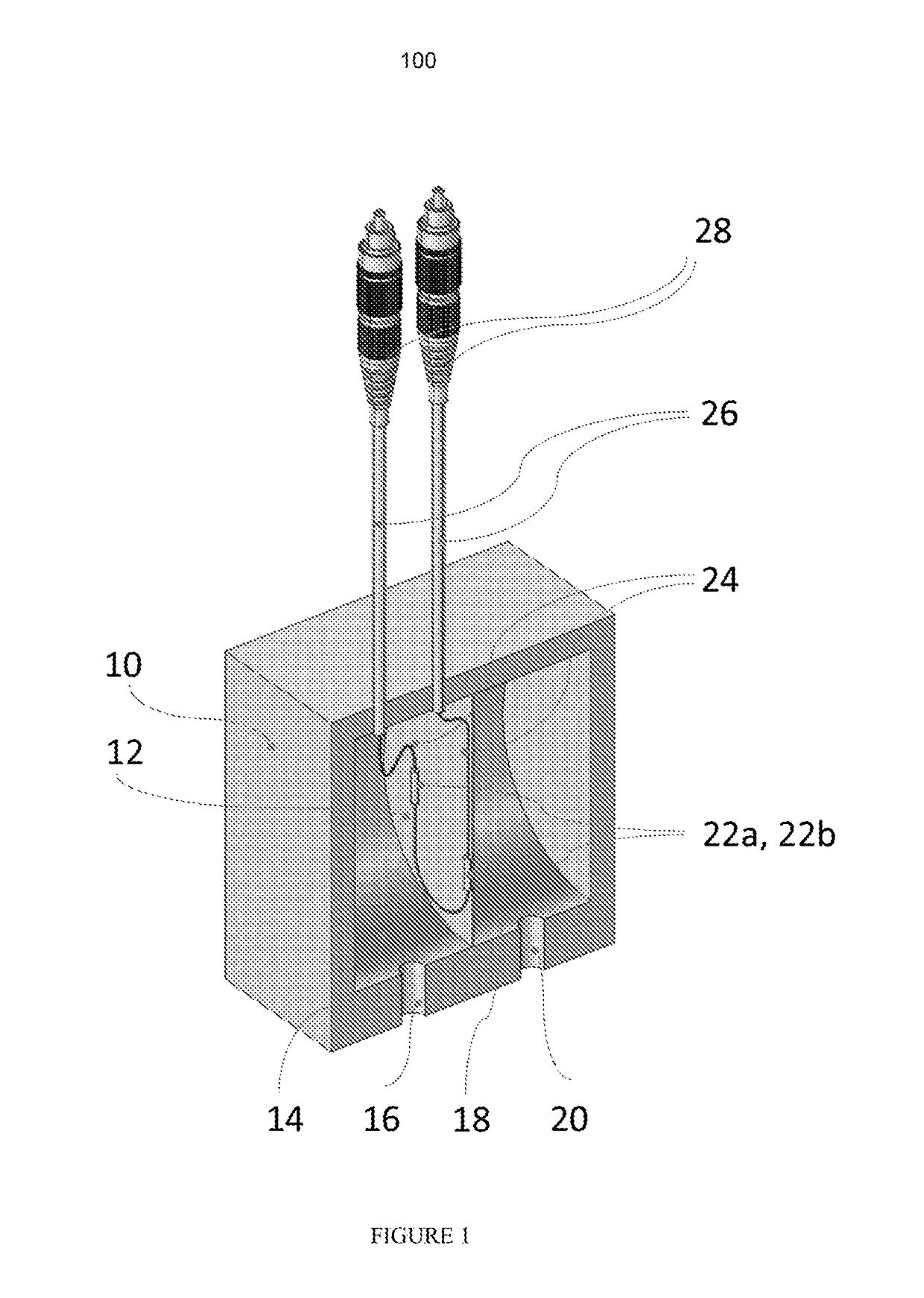
[0060]FIG. 1 shows a perspective cross sectional view of a pressure sensor 100 according to a first exemplary aspect. The pressure sensor comprises a sensor housing 10 and a pressure transmitting element 12 (plate diaphragm) that defines and separates two adjacent, independent pressure chambers 14, 18 each having a respective pressure port 16, 20. The pressure ports fluidically connect the respective chambers to a pressure source(s) being measured (not shown and not part of the invention per se. The sensor housing may be constructed of any suitable material including but not limited to stainless steel, aluminum, or a polymer (e.g., acrylic), depending on the particular application and working environment (i.e., the working pressure range, corrosive or reactive fluids, etc.) as one skilled in the art would understand. The diaphragm 12 may be made of an elastic material including but not limited to stainless steel or a polymer, again depending upon particular applications and working ...


PUM


Abstract

A pressure sensor device includes a pressure chamber housing, at least two separate pressure chambers within the housing, at least one pressure port fluidically coupled to each of the at least two pressure chambers, at least one pressure transmitting element per every two pressure chambers disposed in the pressure chamber, which separates the at least two pressure chambers, and at least two optical sensing elements disposed in at least one of the pressure chambers, wherein the at least two optical sensing elements are each optically coupled to an optical transmission medium.

Description

RELATED APPLICATION DATA[0001]This application claims priority to U.S. Provisional application Ser. 62 / 181,261 filed Jun. 18, 2015, the subject matter of which is incorporated herein by reference in its entirety.BACKGROUND1. Field of the Invention[0002]Embodiments of the invention relate most generally to the field of pressure measurement. More particularly, embodiments and aspects of the invention are directed to fiber optic-based pressure measurement apparatus and methods, and applications including, but not limited to, the direct measurement and / or monitoring of differential pressure, gage pressure, and absolute pressure, as well as the indirect measurement and / or monitoring of fluid flow rate, liquid level, liquid density, fluid flow point velocity (using Pitot tube), filter screen quality monitoring, leak detection, and viscosity measurements.2. Description of the Related Art[0003]Diaphragm pressure sensors are the most common type of pressure sensors used for general purpose p...

Claims


Application Information

Patent Timeline
IPC IPC(8): G01L11/02G01L9/00
CPCG01L11/025G01L9/0076
Inventor ADAMS, CHRISTIANENGLE, DARREN T.RYAN, ROBERT S.WILSON, JODY W.
Owner MULTICORE PHOTONICS INC
Why Eureka
Try Eureka