Calibration Method for a Lithographic Apparatus

a lithographic apparatus and calibration method technology, applied in the field of lithographic apparatuses, can solve the problems of changing the performance of the apparatus, reducing the production throughput of the lithographic apparatus, and overlay errors, so as to reduce the amount of time, improve the accuracy of the lithographic apparatus, and reduce the overlay error

Active Publication Date: 2018-06-21
ASML NETHERLANDS BV
View PDF0 Cites 7 Cited by
  • Summary
  • Abstract
  • Description
  • Claims
  • Application Information

AI Technical Summary

Benefits of technology

[0009]It is therefore desirable to reduce the amount of time required to calibrate a lithographic apparatus. Additionally, it is desirable to improve the accuracy of the lithographic apparatus by reducing the overlay error due to the specific movements of the lithographic apparatus.

Problems solved by technology

A key performance parameter of the lithographic apparatus is the overlay error.
This error, often referred to simply as “overlay”, is the error in placing a product features in the correct position relative to features formed in previous layers.
Changes in the product field size and / or exposure sequence may therefore change the performance of the apparatus.
This directly reduces the production throughput of the lithographic apparatus.

Method used


Image

  • Calibration Method for a Lithographic Apparatus
  • Calibration Method for a Lithographic Apparatus
  • Calibration Method for a Lithographic Apparatus

Examples


Embodiment Construction

[0034]Before describing embodiments of the invention in detail, it is instructive to present an example environment in which embodiments of the present invention may be implemented.

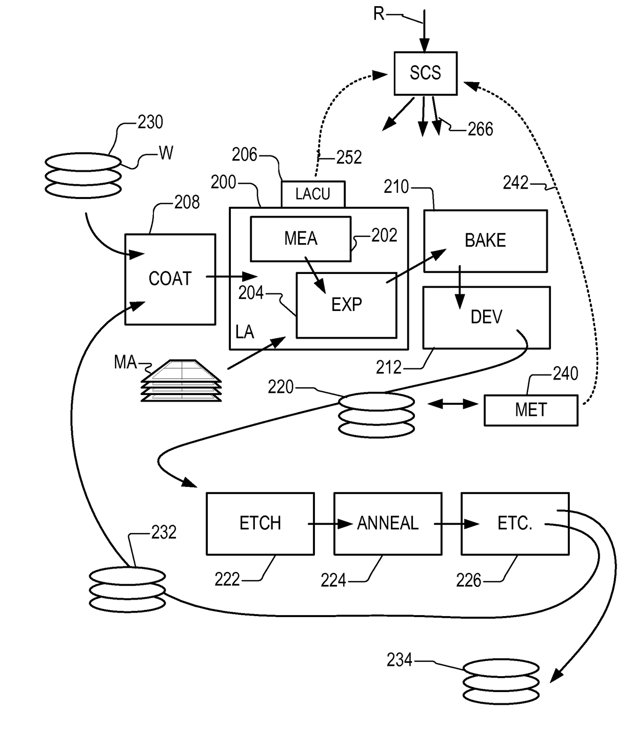
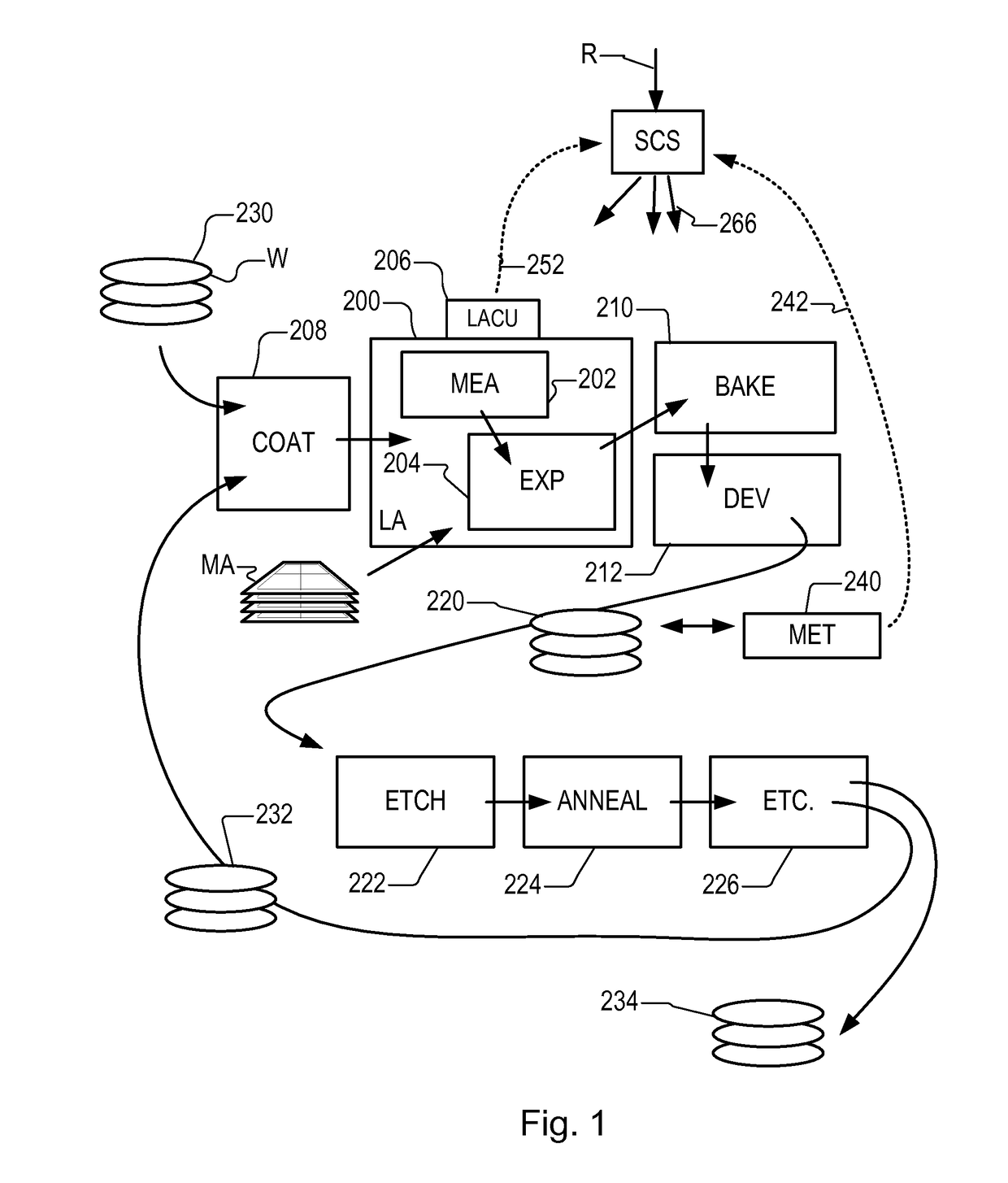
[0035]FIG. 1 at 200 shows a lithographic apparatus LA as part of an industrial production facility implementing a high-volume, lithographic manufacturing process. In the present example, the manufacturing process is adapted for the manufacture of for semiconductor products (integrated circuits) on substrates such as semiconductor wafers. The skilled person will appreciate that a wide variety of products can be manufactured by processing different types of substrates in variants of this process. The production of semiconductor products is used purely as an example which has great commercial significance today.

[0036]Within the lithographic apparatus (or “litho tool”200 for short), a measurement station MEA is shown at 202 and an exposure station EXP is shown at 204. A control unit LACU is shown at 206. In t...


PUM

PropertyMeasurementUnit
wavelengthaaaaaaaaaa

Abstract

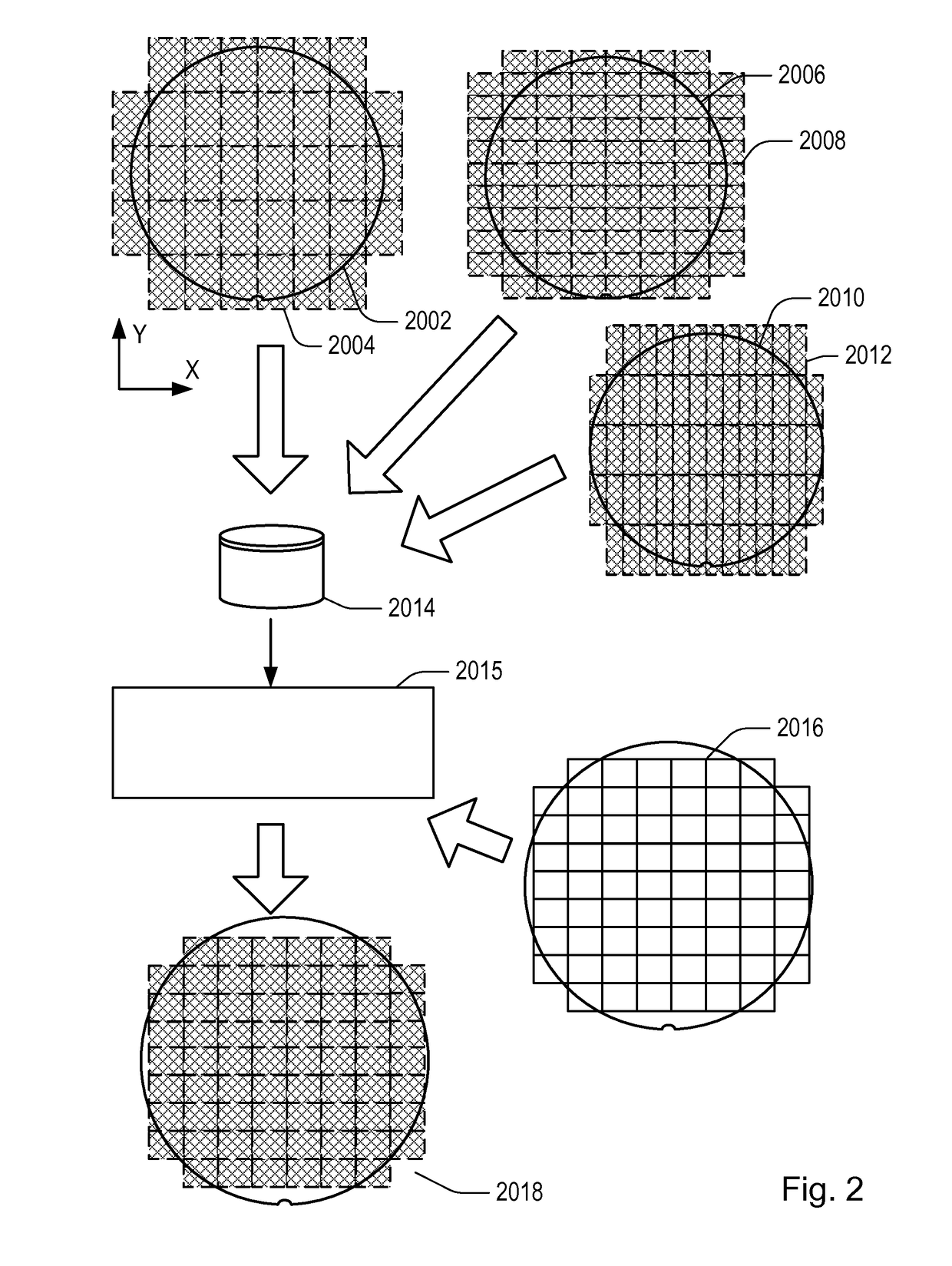
A first substrate (2002) has a calibration pattern applied to a first plurality of fields (2004) by a lithographic apparatus. Further substrates (2006, 2010) have calibration patterns applied to further pluralities of fields (2008, 2012). The different pluralities of fields have different sizes and/or shapes and/or positions. Calibration measurements are performed on the patterned substrates (2002, 2006, 2010) and used to obtain corrections for use in controlling the apparatus when applying product patterns to subsequent substrates. Measurement data representing the performance of the apparatus on fields of two or more different dimensions (2004, 2008, 2012) is gathered together in a database (2013) and used to synthesize the information needed to calibrate the apparatus for a new size. Calibration data is also obtained for different scan and step directions.

Description

CROSS-REFERENCE TO RELATED APPLICATIONS[0001]This application claims priority of EP application 15172798.9 which was filed on Jun. 18, 2015 and EP application 15200409.9 which was filed on Dec. 16, 2015 which are incorporated herein in its entirety by reference.FIELD[0002]The invention relates to lithographic apparatuses, and in particular to calibration methods for lithographic apparatuses and computer program products for implementing such methods. The invention further relates to methods of device manufacture.BACKGROUND[0003]A lithographic process is one that applies a desired pattern onto a substrate, usually onto a target portion of the substrate. A lithographic apparatus can be used, for example, in the manufacture of integrated circuits (ICs). In that instance, a patterning device, which is alternatively referred to as a mask or a reticle, may be used to generate a circuit pattern to be formed on an individual layer of the IC. This pattern can be transferred onto a field (e.g...

Claims


Application Information

Patent Timeline
Patent Type & Authority Applications(United States)
IPC IPC(8): G03F9/00G03F7/20G05B19/4097
CPCG03F9/7019G03F7/705G03F7/70516G03F7/70633G05B19/4097G05B2219/45028G05B2219/45031G05B2219/35012H01L21/0274
Inventor SCHMITT-WEAVER, EMIL PETERSTACKER, JENSSCHREEL, KOENRAAD REMI ANDREWERKMAN, ROY
Owner ASML NETHERLANDS BV
Why Eureka
Try Eureka