Surgical microscope and device for switching the same among multiple working modes

Active Publication Date: 2018-06-28
CARL ZEISS MEDITEC AG
View PDF0 Cites 4 Cited by
  • Summary
  • Abstract
  • Description
  • Claims
  • Application Information

AI Technical Summary

Benefits of technology

[0032]In the surgical microscope and the device for switching the surgical microscope among multiple working modes according to the invention, a plurality of filters are arranged respectively on two or more rotary members which are driven by the same power source to rotate synchronously, so that when the surgical microscope is switched among different working modes, it is possible to control the respective filters, using a single power source, to accurately move into or out of the illumination beam path or the observation beam path, t

Problems solved by technology

Manual and separate movement of the filters results in complex, time-consuming, troublesome and inaccurate operations.
Automatic movement of the filters by motors requires

Method used


Image

  • Surgical microscope and device for switching the same among multiple working modes
  • Surgical microscope and device for switching the same among multiple working modes
  • Surgical microscope and device for switching the same among multiple working modes

Examples


Example

[0042]The surgical microscope and the device for switching the surgical microscope among multiple working modes according to embodiments of the invention will be illustrated below with reference to the drawings.

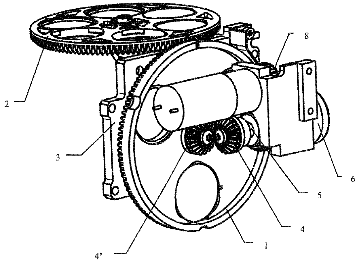
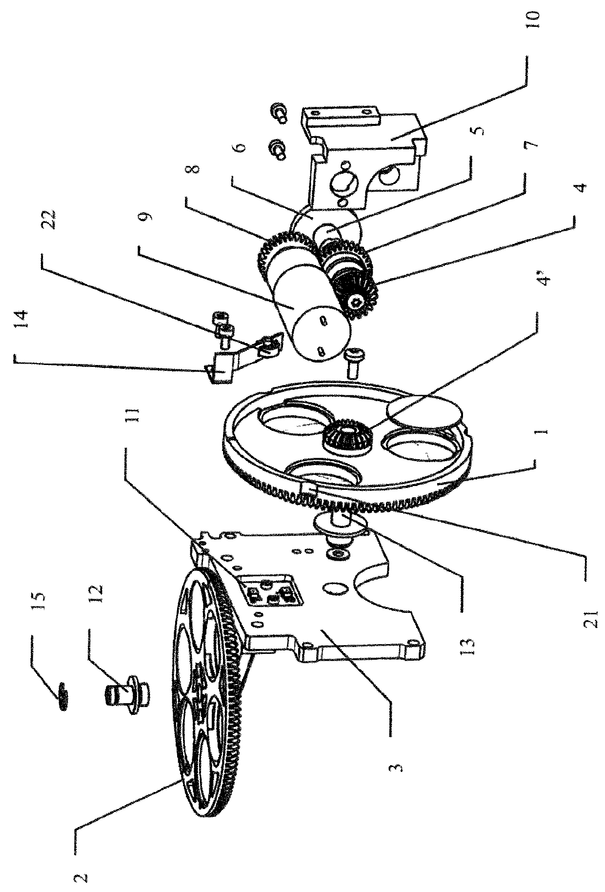
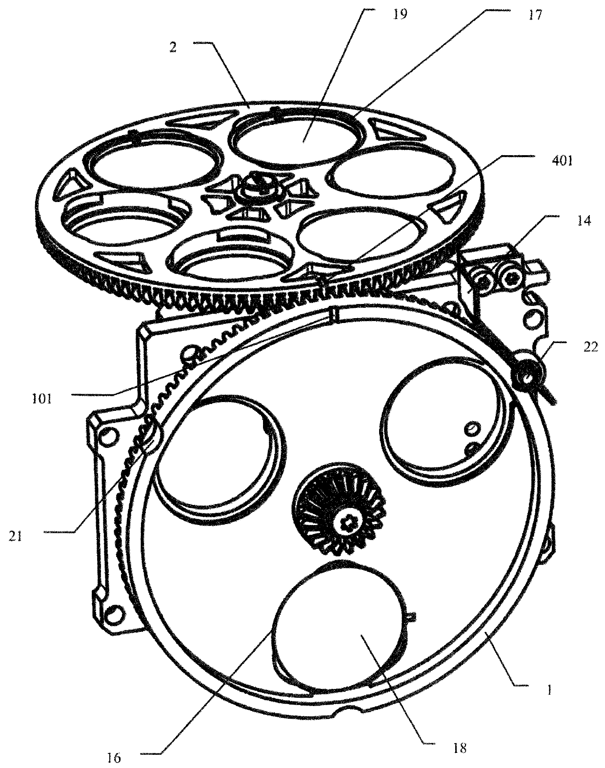
[0043]As shown in FIGS. 1 to 3, the device for switching the surgical microscope among multiple working modes according to an embodiment of the invention mainly includes two rotary members 1 and 2 arranged in an illumination beam path and an observation beam path, respectively. The two rotor members 1 and 2 are driven by the same power source to rotate synchronously among multiple rotary positions corresponding to the multiple working modes. The term “rotary position” in the invention refers to an angular position of the rotary member 1 and / or 2 in respective rotary directions (circumferential direction).

[0044]In the invention, the illumination beam path refers to a path traveled by a light that is emitted from a light source of the surgical microscope, passes a series of opt...


PUM


Abstract

The invention is directed to a surgical microscope and a device for switching the same among multiple working modes. The device includes an illumination rotary member and an observation rotary member that are arranged, respectively, in the illumination beam path and the observation beam path of the surgical microscope and are drivable by the same power source to rotate synchronously among multiple rotary positions corresponding to the multiple working modes. In each of the rotary positions, light from a light source of the surgical microscope passes through one or more of multiple light-through-portions of the illumination rotary member along the illumination beam path to illuminate the observed object, and then passes through one or more of multiple light-through-portions of the observation rotary member along the observation beam path to reach the eyepiece and/or an observation instrument of the surgical microscope.

Description

CROSS REFERENCE TO RELATED APPLICATION[0001]This application claims priority of Chinese patent application no. 2016 11 208 161.5, filed Dec. 23, 2016, Chinese patent application no. 2017 10 019 640.0, filed Jan. 11, 2017, and Chinese Utility Model 2017 20 031 205.5, filed Jan. 11, 2017 and the entire content of the above applications is incorporated herein by reference.FIELD OF THE INVENTION[0002]The invention relates to a surgical microscope, and more specifically to a device for switching a surgical microscope among multiple working modes. The invention further relates to solutions of optical application of the surgical microscope.BACKGROUND OF THE INVENTION[0003]Filters are used in some surgical microscopes to select lights with different spectral characteristics, polarization states or phase properties, which lights are reflected, refracted, absorbed, diffused or manifest other optical properties differently in different media or media interfaces. As a result of this, the surgic...

Claims


Application Information

Patent Timeline
IPC IPC(8): G02B21/00G02B21/06G02B5/30G02B21/16G02B27/22G02B21/02G01D5/14G01D5/34
CPCG02B21/0012G02B21/06G02B5/3025G02B21/16G02B27/2228G02B21/025G01D5/145G01D5/342A61C19/00A61B90/20G02B21/0004G02B21/248G02B21/22G02B30/34
Inventor MA, TAOJIN, JIANGONG, QUANRONGZHANG, XIANGXIANG
Owner CARL ZEISS MEDITEC AG
Why Eureka
Try Eureka