Supercharge Your Innovation With Domain-Expert AI Agents!

Gate driver on array circuit and LCD panel

Active Publication Date: 2018-06-28
WUHAN CHINA STAR OPTOELECTRONICS TECH CO LTD
View PDF2 Cites 2 Cited by
  • Summary
  • Abstract
  • Description
  • Claims
  • Application Information

AI Technical Summary

Benefits of technology

The present invention aims to provide a new gateway driver circuit and liquid crystal display panel that reduces the power dissipation of the panel. This is as traditional gateway driver circuits have high power dissipation, which results in high power consumption. The new invention uses two high-level signal sources, which in effect reduces the overall power dissipation of the gateway driver circuit and solves the issue of high power dissipation of the conventional panel.

Problems solved by technology

This causes power dissipation generated in driving the logic unit by the GOA circuit to be too high, further causing power dissipation of the corresponding liquid crystal display (LCD) panel to be too high.

Method used


Image

  • Gate driver on array circuit and LCD panel
  • Gate driver on array circuit and LCD panel
  • Gate driver on array circuit and LCD panel

Examples


Embodiment Construction

[0131]The following description of every embodiment with reference to the accompanying drawings is used to exemplify a specific embodiment, which may be carried out in the present invention. Directional terms mentioned in the present invention, such as “top”, “bottom”, “front”, “back”, “left”, “right”, “inside”, “outside”, “side” etc., are only used with reference to the orientation of the accompanying drawings. Therefore, the used directional terms are intended to illustrate, but not to limit, the present invention.

[0132]In the drawings, the components having similar structures are denoted by the same numerals.

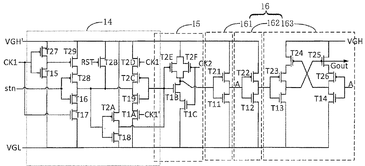
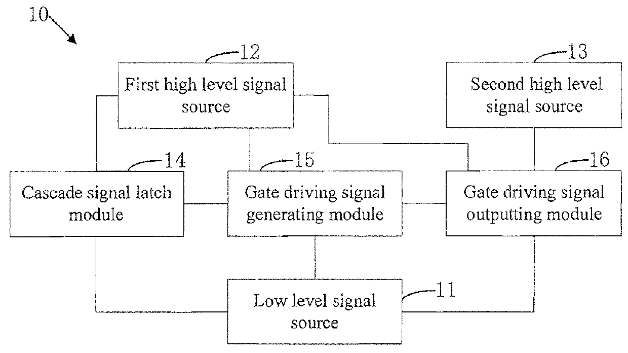
[0133]As shown in FIG. 1, FIG. 1 is a structural diagram of a preferred embodiment of a gate driver on array (GOA) circuit of the present disclosure. The GOA circuit 10 of the preferred embodiment of the present disclosure comprises a low level signal source 11, a first high level signal source 12, a second high level signal source 13, a cascade signal latch module 14, a gate...


PUM


Abstract

The present disclosure provides a gate driver on array (GOA) circuit. A low level signal source is used to output a low level signal, a first high level signal source is used to output a first high level signal, and the second high level signal source is used to output the second high level signal. A cascade signal latch module is used to latch a cascade signal of a current grade. A gate driving signal generating module generates a preparation gate driving signal of the current grade. A gate driving signal outputting module is used to output a gate driving signal of the current grade.

Description

BACKGROUND OF THE INVENTION1. Field of the Invention[0001]The present disclosure relates to the field of display drivers, and more particularly to a gate driver on array (GOA) circuit and a liquid crystal display (LCD) panel.2. Description of the Prior Art[0002]A gate driver on array circuit, abbreviated as GOA circuit, uses that a scan driving circuit is formed on an array substrate by processing of an array substrate of a traditional thin film transistor-liquid crystal display (TFT-LCD), thus, driving scan lines row by row is achieved.[0003]Not only does the GOA circuit have cascade signal and timing signals, but the GOA circuit also has high level signals and low level signals. The high level signal is used to drive a logic unit in the circuit and also is used to drive an output unit in the circuit.[0004]As a conventional GOA circuit uses a same high level signal to drive the logic unit and the output unit in the circuit, however, voltage for driving the high level signal of the ...

Claims


Application Information

Patent Timeline
IPC IPC(8): G09G3/36G02F1/1345G02F1/1362
CPCG09G3/3677G02F1/13454G02F1/136286G09G2330/021G09G2310/06G09G2310/0289G09G2310/0243G09G3/3648G09G2310/0286G09G3/3696G09G2330/028
Inventor GONG, QIANGCHEN, GUIWANG, CHAO
Owner WUHAN CHINA STAR OPTOELECTRONICS TECH CO LTD
Features
  • R&D
  • Intellectual Property
  • Life Sciences
  • Materials
  • Tech Scout
  • Unparalleled Data Quality
  • Higher Quality Content
  • 60% Fewer Hallucinations
Learn More