Stator arrangement, electric three-phase generator and method for producing a stator arrangement

a stator arrangement and electric three-phase generator technology, applied in the direction of dynamo-electric machines, electrical apparatus, magnetic circuit shapes/forms/construction, etc., can solve the problem of high cost of forming said star points, and achieve the effect of preventing errors in winding stator teeth and increasing the operational reliability of electric machines

Active Publication Date: 2018-06-28
BROSE FAHRZEUGTEILE GMBH & CO KG
View PDF10 Cites 12 Cited by
  • Summary
  • Abstract
  • Description
  • Claims
  • Application Information

AI Technical Summary

Benefits of technology

[0023]In another advantageous embodiment, the contacting device comprises a plurality of wire feedthroughs which are provided on the outer surface of the contacting device on the side remote from the stator teeth and which are designed to feed the winding wire through the contacting device. The wire feedthroughs are advantageously designed as slots which have a predetermined length, in order to position the winding wire with respect to a wire guide. In this way, errors when winding the stator teeth can be prevented, since the slots arrange the winding wire on the predetermined wire guide series.
[0024]In another advantageous embodiment, at least one additional connecting...

Problems solved by technology

Forming said star point is expensive si...

Method used


Image

  • Stator arrangement, electric three-phase generator and method for producing a stator arrangement
  • Stator arrangement, electric three-phase generator and method for producing a stator arrangement
  • Stator arrangement, electric three-phase generator and method for producing a stator arrangement

Examples


first embodiment

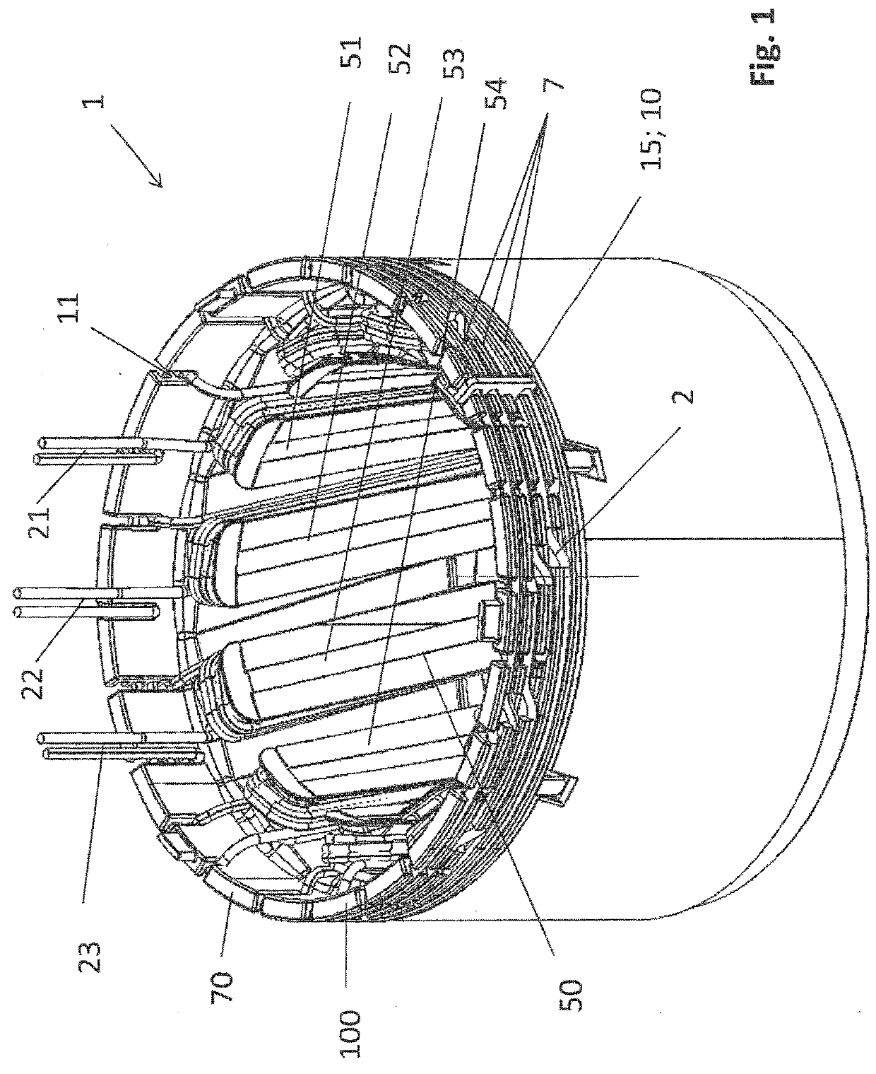
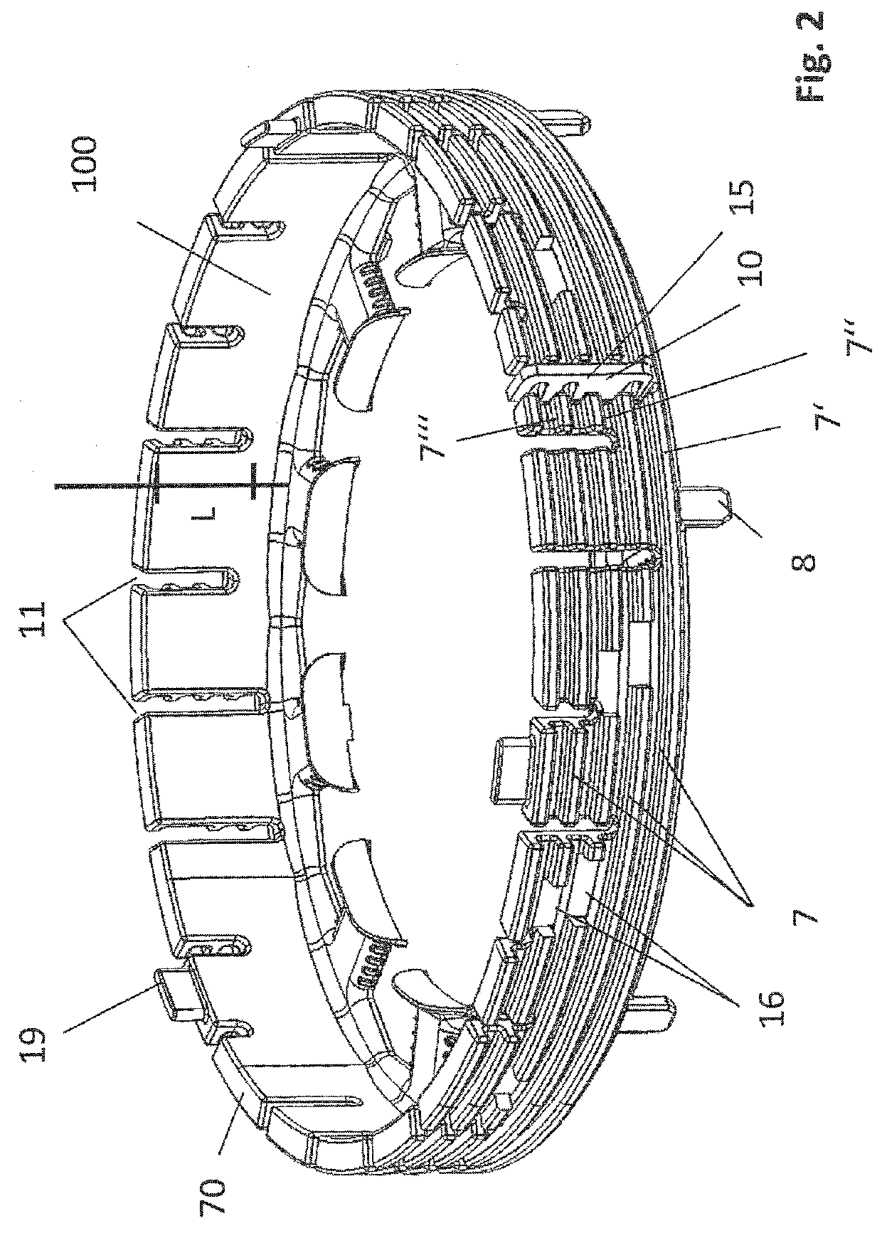
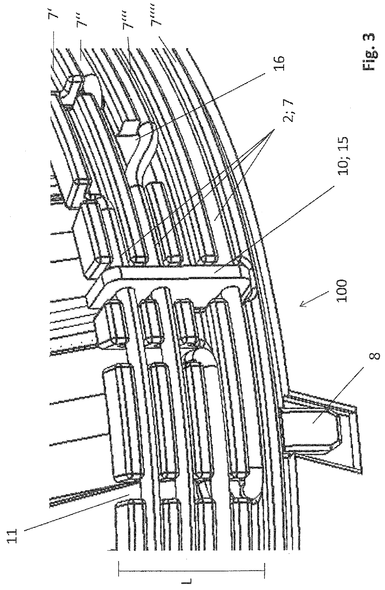
[0044]FIG. 1 is a perspective view of a stator arrangement 1 according to the invention for an electric machine according to a The stator arrangement 1 comprises, for example, a laminated stator core 50, which comprises a plurality of stator teeth 51; 52; 53; 54. On the laminated stator core 50, a contacting device 100 is arranged on an end portion of the stator teeth 51; 52; 53; 54. The contacting device 100 comprises an annular main body 70, which is made of a plastics material, for example. The stator arrangement 1 comprises a continuously wound winding wire 2 which is wound in each case about individual stator teeth 51; 52; 53; 54 in order to form stator tooth windings and portions of which are arranged on the contacting device 100 between the stator teeth.

[0045]In addition, a connecting element 10 is provided, which is arranged on the contacting device 100 and designed to electrically connect portions of the winding wire 2 arranged near to the contacting device 100 in order to...

second embodiment

[0064]FIG. 13 is a perspective view of the contacting device 100 according to the invention according to the In this view, the connecting element 90 and the connecting element 10 can be seen clearly. The connecting element 90 and the connecting element 10 are each designed as wire portions and are fastened around the corresponding portions of the winding wire 2 in order to electrically connect the corresponding portions. For example, the connecting elements 10 and 90 are hot-caulked to the corresponding portions of the winding wire. A first star point 15 and another star point 95 are formed in this way. This results in two star connections which are connected in parallel. This design increases the operational reliability of the stator arrangement since two redundant star connections are produced. The connecting element 10 and / or the connecting element 90 can also be designed as insulation displacement contacts or as a welded joint.

[0065]FIG. 14 is a view of a section of a contactin...


PUM


Abstract

The present invention provides a stator arrangement for an electric three-phase generator, comprising a plurality of stator teeth, comprising a contacting device which is arranged on an end portion of the stator teeth, comprising a continuously wound winding wire which is wound in each case about individual stator teeth in order to form stator tooth windings and portions of which are arranged on the contacting device between the individual stator teeth, comprising a connecting element, which is arranged on the contacting device and designed to electrically connect portions of the winding wire arranged on the contacting device in order to form a star point. The present invention further provides an electric three-phase generator and a method for producing a stator arrangement.

Description

FIELD OF THE INVENTION[0001]The present invention relates to a stator arrangement, to an electric three-phase generator and to a method for producing a stator arrangement.TECHNICAL BACKGROUND[0002]Electric motors are electric machines which can be found in many forms. Electric motors having a star connection can thus also be found. A star connection of this kind is the interconnection of, for example, three connections via a resistor at a common point. The resulting combination forms the centre point, which is also referred to as the star point or neutral point. A star point connection has the advantage that for symmetric loading, that is to say the three load phase windings each have the same impedance, it is possible to tap two different voltages.[0003]For electric motors, a switch wafer is sometimes used for the stator windings of the star point connection. In this case, it is necessary for each individual stator winding to be wound by its own winding wire and contacted at the st...

Claims


Application Information

Patent Timeline
IPC IPC(8): H02K3/28H02K1/16H02K3/12H02K15/02H02K15/085
CPCH02K3/28H02K1/16H02K3/12H02K15/024H02K15/085H02K2203/06H02K3/522
Inventor WUST, STEFANFIEDERLING, DANIELSTRAUSS, WOLFGANG
Owner BROSE FAHRZEUGTEILE GMBH & CO KG
Why Eureka
Try Eureka