System and method for breast imaging

a breast imaging and system technology, applied in the field of breast imaging systems, can solve the problems of significant discrepancies, unnecessary biopsies, and difficult registration of the two imaging modalities

Active Publication Date: 2018-07-05
GENERAL ELECTRIC CO
View PDF1 Cites 12 Cited by
  • Summary
  • Abstract
  • Description
  • Claims
  • Application Information

AI Technical Summary

Problems solved by technology

Such shifting of position of the patient shifts the shape and the tissue of the breast making any registration of the two imaging modalities difficult.
As a result, significant discrepancies between the findings in the mammography and the ultrasound images may require further imaging to resolve and my lead to unnecessary biopsies.
However, if the ultrasound gel is applied to the breast prior to taking the x-ray image it may result in artifacts in the x-ray image.
Previous attempts to design breast screening systems that integrate both x-ray and ultrasound technologies have had not completely addressed the workflow and image quality needed in both the mammography and ultrasound.
However, the ultrasound image quality is degraded as resolution is limited by the frequency of the ultrasound due to an inverse relationship between the frequency of the ultrasound signals and the penetration depth of the sound waves, i.e., the sound attenuation is proportional to the frequency and higher frequency ultrasound may not adequately penetrate the breast tissue.
In most breast-compressed thicknesses the ultrasound frequency needed to fully penetrate the breast does not give sufficient imaging resolution to detect small masses and calcifications.
This results in necessitating a higher x-ray dose to the patient.
This may result in degradation of the x-ray image quality as well.
However, the workflow and image registration have proven difficult, since movement of the breast being imaged is likely.

Method used


Image

  • System and method for breast imaging
  • System and method for breast imaging
  • System and method for breast imaging

Examples


Embodiment Construction

[0029]In the following specification and the claims, reference will be made to a number of terms, which shall be defined to have the following meanings.

[0030]The singular forms “a”, “an”, and “the” include plural references unless the context clearly dictates otherwise.

[0031]“Optional” or “optionally” means that the subsequently described event or circumstance may or may not occur, and that the description includes instances where the event occurs and instances where it does not.

[0032]Approximating language, as used herein throughout the specification and claims, may be applied to modify any quantitative representation that could permissibly vary without resulting in a change in the basic function to which it is related. Accordingly, a value modified by a term or terms, such as “about”, “approximately”, and “substantially”, are not to be limited to the precise value specified. In at least some instances, the approximating language may correspond to the precision of an instrument for...


PUM


Abstract

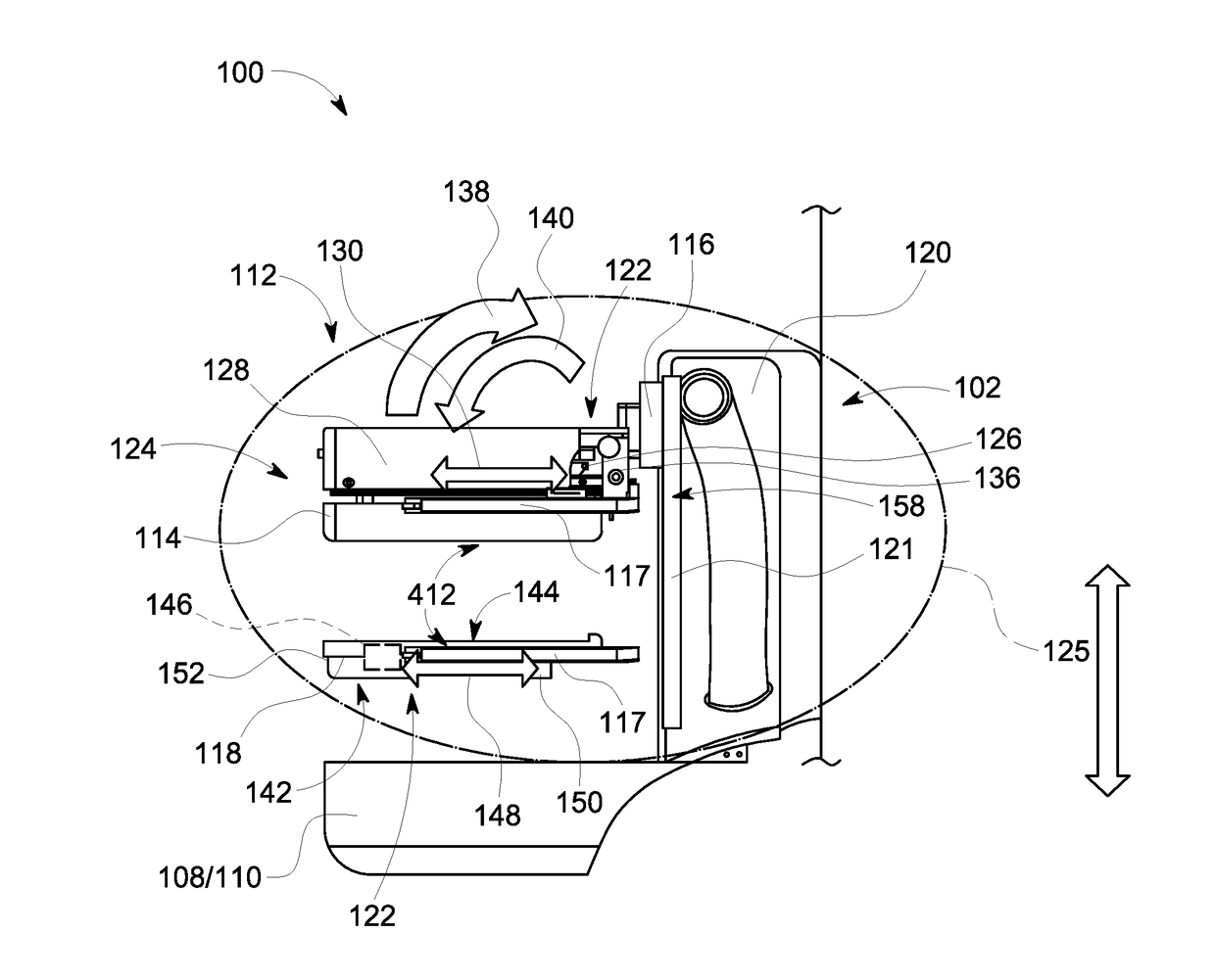
An imaging assembly includes a compression system configured to receive and compress an object to be imaged. The compression system includes a first compression paddle and a second compression paddle. The imaging assembly further includes an ultrasound system including a first ultrasound probe coupled to the first compression paddle. The first ultrasound probe is configured to acquire a first portion of the ultrasound image information of the object. The ultrasound system also includes a second ultrasound probe coupled to the second compression paddle. The second ultrasound probe is configured to acquire a second portion of the ultrasound image information of the object.

Description

BACKGROUND[0001]The field of the disclosure relates generally to breast imaging systems, and, more particularly, to breast imaging systems including ultrasound and x-ray using a dual-sided compression paddle system and the methods of operation for acquiring breast images.[0002]Breast cancer screening is performed with x-ray imaging in either two-dimensional, i.e., mammography, and in recent years, tomosynthesis (three-dimensional x-ray). For many women, such x-ray screening is sufficient for generating images that are satisfactory for review by a medical professional. However, many women have a high percentage of dense breast tissues which do not show contrast versus cancerous tissues and additional screening is performed through ultrasound imaging. Ultrasound imaging is often performed in a supine position whereas the x-ray mammography is performed with the women upright with the breast in a compressed position. Such shifting of position of the patient shifts the shape and the tiss...

Claims


Application Information

Patent Timeline
Patent Type & Authority Applications(United States)
IPC IPC(8): A61B6/00A61B8/00A61B8/08A61B6/04
CPCA61B6/502A61B6/547A61B6/4417A61B6/4435A61B8/0825A61B6/0414A61B8/403A61B6/025A61B8/4416
Inventor DAVIS, CYNTHIA ELIZABETH LANDBERGMAO, YINGCARSON, PAUL LANGFORDKRIPFGANS, OLIVER DANIELFOWLKES, JEFFREY BRIAN
Owner GENERAL ELECTRIC CO
Why Eureka
Try Eureka