Method of heat treatment

Active Publication Date: 2018-07-05
ROLLS-ROYCE SMR LTD
View PDF2 Cites 1 Cited by
  • Summary
  • Abstract
  • Description
  • Claims
  • Application Information

AI Technical Summary

Benefits of technology

[0017]The thermocouples may be sprung so as to impr

Problems solved by technology

The described methods of post-weld heat treatment

Method used


Image

  • Method of heat treatment
  • Method of heat treatment
  • Method of heat treatment

Examples


Example

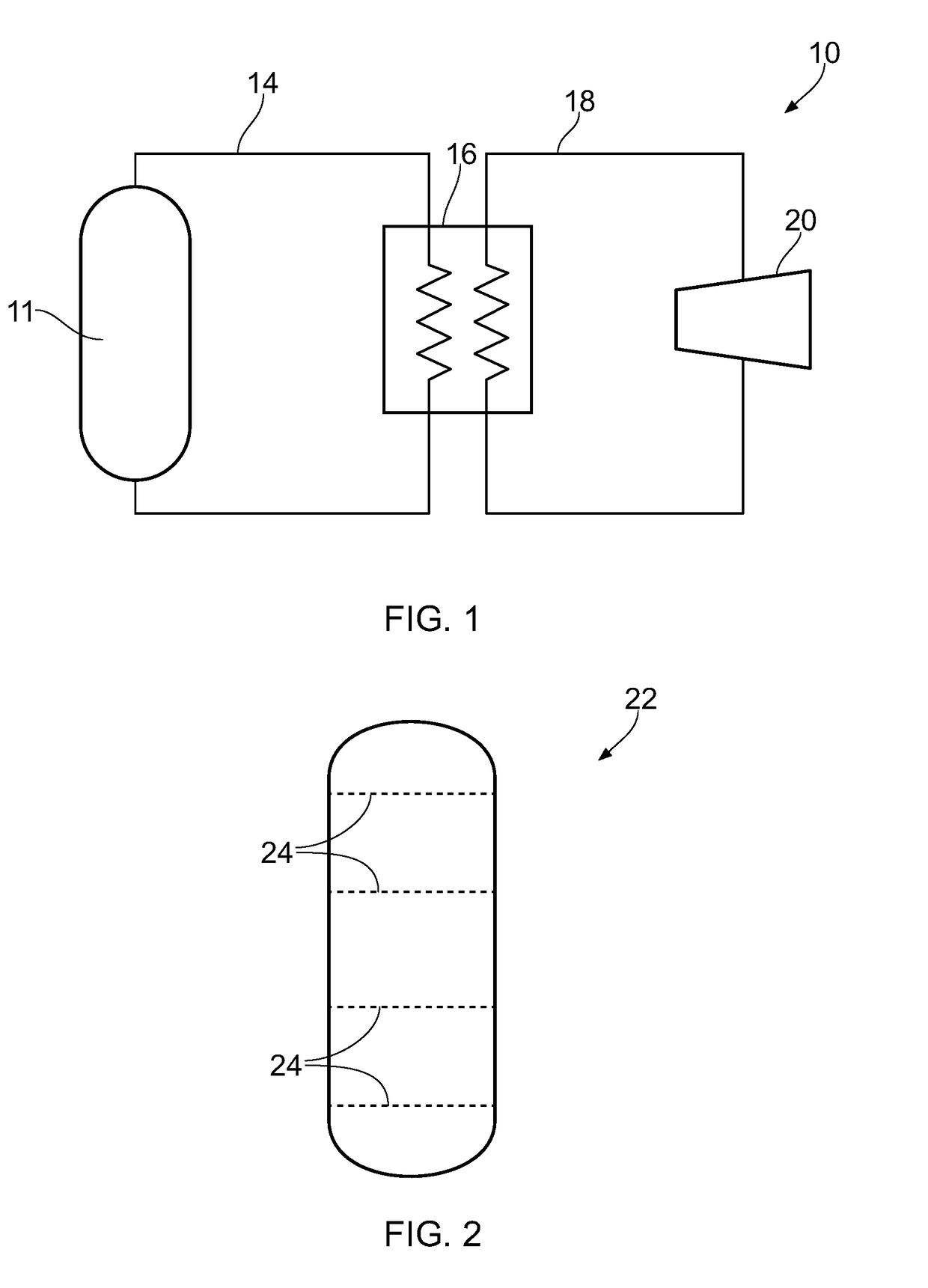
[0054]Referring to FIG. 1, a nuclear power plant is indicated generally at 10. The plant includes a nuclear reactor 11, a primary circuit 14, a steam generator 16, a secondary circuit 18 and a turbine 20. The primary fluid in the primary circuit is heated by the nuclear reactor. The nuclear reactor includes a nuclear reactor vessel that houses nuclear fuel. The primary fluid then flows to the steam generator, where it heats secondary fluid in the secondary circuit. The heated secondary fluid is then used to drive the turbine 20.

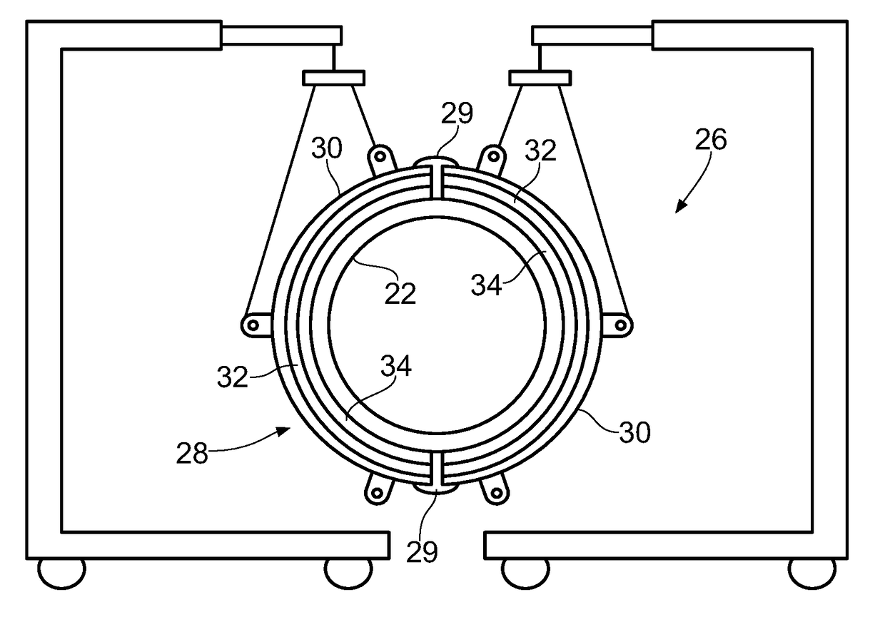
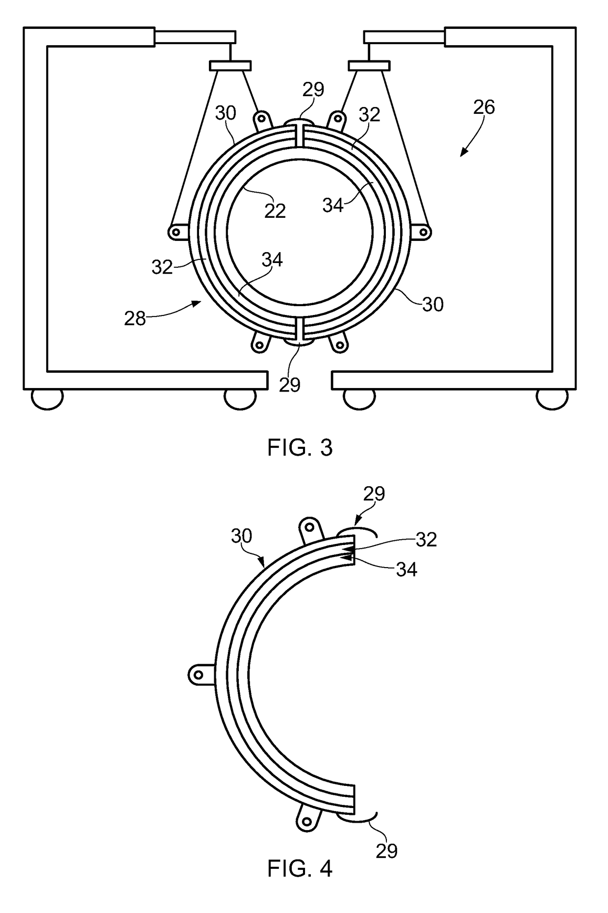
[0055]Referring to FIG. 2, pressure vessels 22 such as the reactor vessel or the steam generator vessel are often fabricated from a plurality of sections that are welded together, for example at the lines indicated at 24 in FIG. 2. Before and / or after welding (i.e. pre-weld or post-weld) the weld region needs to be heat treated. Before welding, the weld region is considered to be the ends of the sections that are to be welded together, and after welding, the ...


PUM

PropertyMeasurementUnit
Angleaaaaaaaaaa
Angleaaaaaaaaaa

Abstract

A method of heat treating a localised region of a component including providing a heat treatment assembly with two or more subassemblies. Each subassembly is configured to partially circumscribe a portion of the component for heat treatment. Each subassembly includes a housing configured to partially circumscribe a portion of the component. An insulator and a heater are provided within the housing and extend to partially circumscribe a component and are arranged such that the insulator is between a wall of the housing and the heater. The method includes positioning the subassemblies adjacently around the component so that the subassemblies fully circumscribe the component. The subassemblies are connected together. The method includes activating the heater to heat the component in a region adjacent the heater.

Description

CROSS-REFERENCE TO RELATED APPLICATION[0001]This specification is based upon and claims the benefit of priority from UK Patent Application Number 1621951.1 filed on 22 Dec. 2016, the entire contents of which are incorporated herein by reference.BACKGROUND1. Field of the Disclosure[0002]The present disclosure concerns a method of heat treating a localised region of a component, a method of manufacturing a component, and / or a heat treatment assembly.2. Description of the Related Art[0003]When components are welded together, particularly thick walled components such as those used for pressure vessels, the components often need to be heated before welding and / or the weld needs to be heat treated after welding, referred to as post weld heat treatment.[0004]There are several methods of post weld heat treatment, depending on the diameter of the component being welded and subsequently heat treated. For smaller components, the weld is visually inspected and then thermocouples are manually at...

Claims


Application Information

Patent Timeline
IPC IPC(8): C21D9/50C21D9/00C21D1/40
CPCC21D9/50C21D9/0006C21D1/40C21D2221/00C21D2251/04H05B3/28H05B3/141H05B3/58C21D9/08
Inventor HIND, LAURA M.TSAO, VINCENT P.JACKSON, CALLUM J.CLARK, DANIELCHAN, WAI LEK
Owner ROLLS-ROYCE SMR LTD
Why Eureka
Try Eureka