


Quick Research
Generate reliable direction feasibility study reports for your R&D in just a few steps.

Technical Q&A
Discover and master advanced knowledge NOW. Basics, ideas, possibilities, all at once.

Find Solutions
As an expert in R&D theories, this can generate solutions to your technical problems instantly.

Evaluate Feasibility
Analyze your overall solution with one click, know your potential R&D risks in advance.

Monitor Landscape
Get weekly tech updates, stay abreast of the latest tech innovations and key insights.
Ultrasonic Probe and Ultrasonic Inspection Apparatus
an ultrasonic and ultrasonic technology, applied in the direction of instruments, piezoelectric/electrostrictive transducers, transducer types, etc., can solve the problems of inability to realistically achieve the method, the electronic components are subjected to miniaturization, and the package is also subject to diversification and complication. achieve the effect of improving the impedance matching state and easy formation
- Summary
- Abstract
- Description
- Claims
- Application Information
AI Technical Summary
Benefits of technology
Problems solved by technology
Method used
Image

Examples
first embodiment
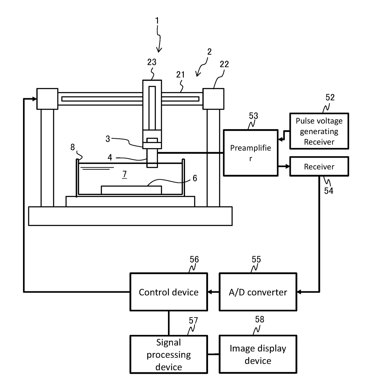
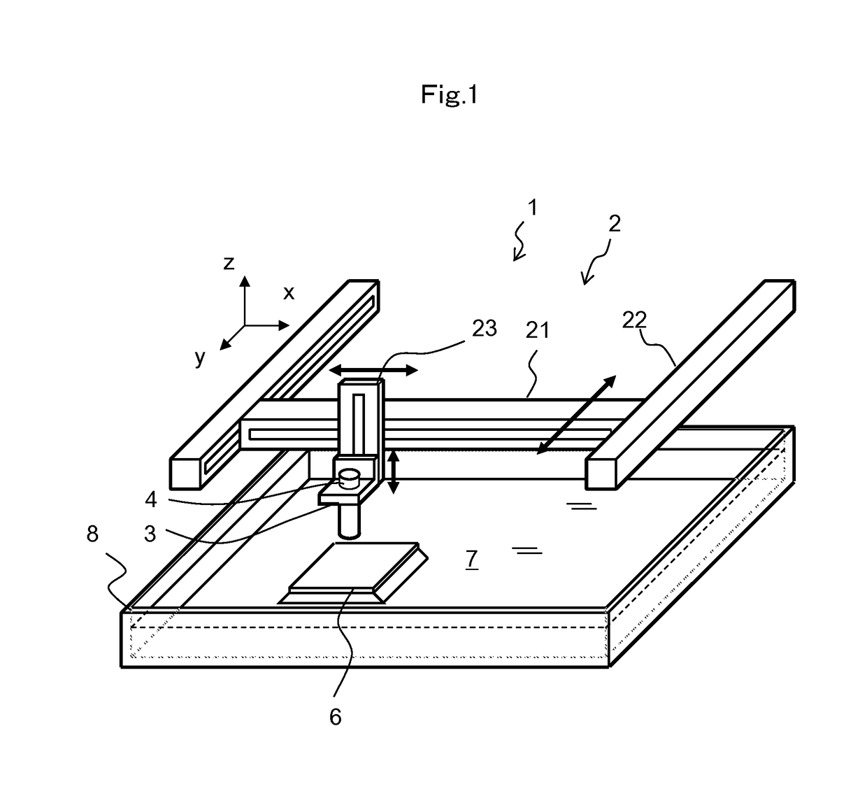
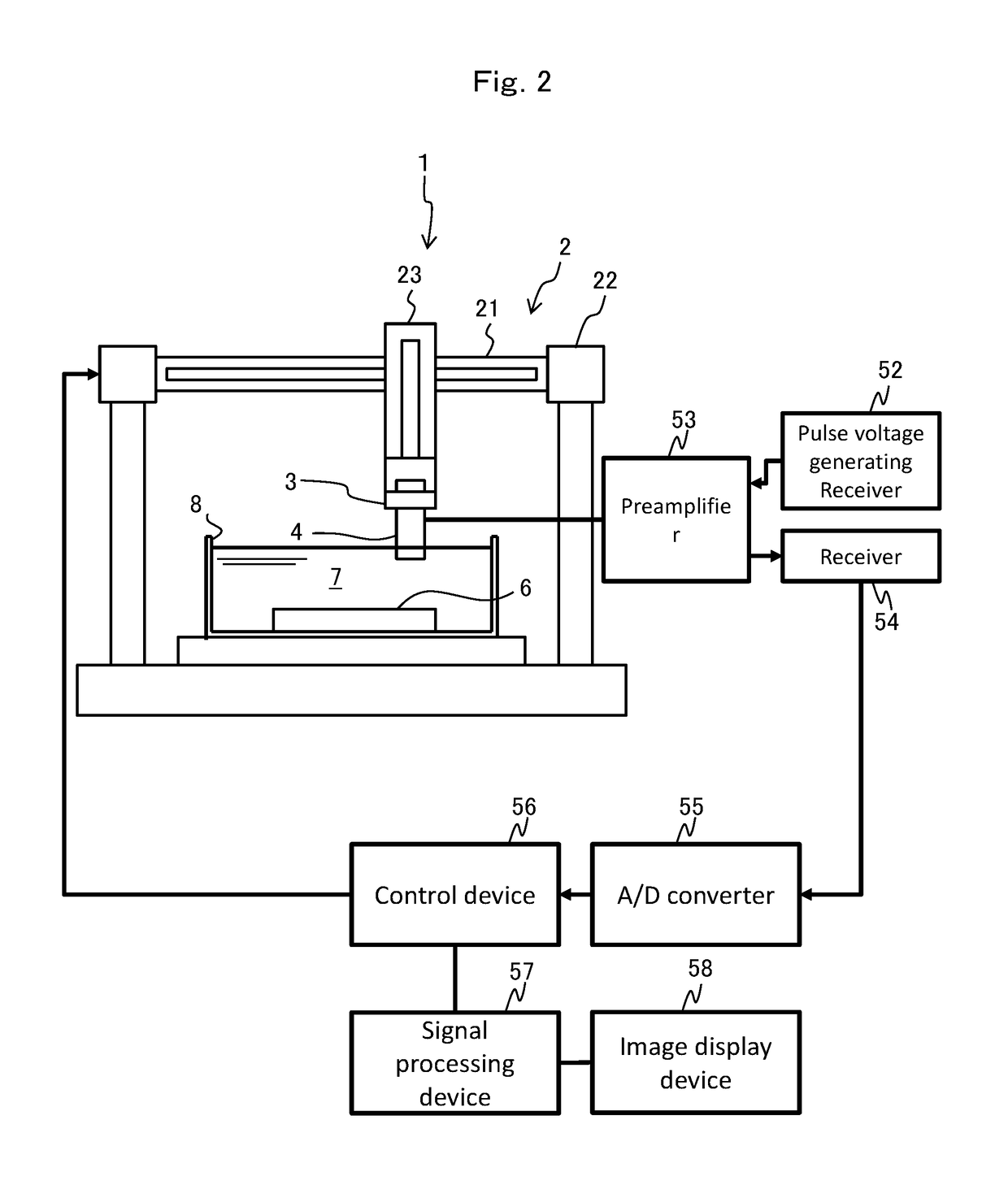
[0026]FIG. 1 is a perspective view illustrating an external appearance of the ultrasonic inspection apparatus 1.
[0027]The ultrasonic inspection apparatus 1 includes a three axis scanner 2 (scanning means), an ultrasonic probe 4, and a holder 3 holding the ultrasonic probe 4. The three axis scanner 2 is configured to include an x-axis scanner 21, a y-axis scanner 22, and a z-axis scanner 23. The z-axis scanner 23 is attached to the x-axis scanner 21, and the x-axis scanner 21 is attached to the y-axis scanner 22. The three axis scanner 2 adjusts the height of the ultrasonic probe 4 with respect to a planar inspection target 6 to scan the inspection target 6 in a two-dimensional manner. This allows the ultrasonic inspection apparatus 1 to visualize the planar inspection target 6 with the ultrasonic wave.
[0028]The ultrasonic probe 4 is attached to the three axis scanner 2 by the holder 3. The three axis scanner 2 scans the ultrasonic probe 4 in the two-dimensional manner and detects th...
second embodiment
[0071]In the first embodiment, a case is described where two layers of the piezoelectric layers are stacked. In the second embodiment, three layers of the piezoelectric layers are stacked.
[0072]FIG. 9 is a cross-sectional view illustrating a configuration of the stacked piezoelectric element 40A in the second embodiment.
[0073]The stacked piezoelectric element 40A includes a stacked piezoelectric film 48A between the lower electrode 42 and the upper electrode 49. The stacked piezoelectric film 48A includes: a ZnO film 43 (first piezoelectric layer) having a c-axis whose direction is oriented in one direction approximately perpendicular to the surface of the piezoelectric thin film to have spontaneous polarization in which the upper surface side has O polarity; a ScAlN film (second piezoelectric layer) directly formed on the ZnO film 43, the ScAlN film 44 having a c-axis whose direction is oriented in one direction approximately perpendicular to the surface of the piezoelectric thin f...
third embodiment
[0075]In the third embodiment, furthermore, four layers of the piezoelectric layers are stacked.
[0076]FIG. 10 is a cross-sectional view illustrating a configuration of the stacked piezoelectric element 40B in the third embodiment.
[0077]The stacked piezoelectric element 40B includes a stacked piezoelectric film 48B between the lower electrode 42 and the upper electrode 49. The stacked piezoelectric film 48B includes: a ZnO film 43 (first piezoelectric layer) having a c-axis whose direction is oriented in one direction approximately perpendicular to the surface of the piezoelectric thin film to have spontaneous polarization in which the upper surface side has O polarity; a ScAlN film (second piezoelectric layer) directly formed on the ZnO film 43, the ScAlN film 44 having a c-axis whose direction is oriented in one direction approximately perpendicular to the surface of the piezoelectric thin film and having spontaneous polarization in the opposite direction to the Zn0; a ZnO film 45 ...
PUM
 Abstract
Description
Claims
Application Information
 - R&D Engineer
- R&D Manager
- IP Professional
- Industry Leading Data Capabilities
- Powerful AI technology
- Patent DNA Extraction
Browse by: Latest US Patents, China's latest patents, Technical Efficacy Thesaurus, Application Domain, Technology Topic, Popular Technical Reports.
© 2024 PatSnap. All rights reserved.Legal|Privacy policy|Modern Slavery Act Transparency Statement|Sitemap|About US| Contact US: help@patsnap.com