Computerized testing and determination of a visual field of a patient

Active Publication Date: 2018-07-12
VISIBLY INC
View PDF5 Cites 2 Cited by
  • Summary
  • Abstract
  • Description
  • Claims
  • Application Information

AI Technical Summary

Benefits of technology

The present patent is about a system and method for measuring the refractive error of a patient using a computerized screen and providing them with a corrective lenses prescription. This system and method offer convenience, cost-effectiveness, and can accurately determine the axial and cylinder astigmatism prescriptions of a patient. The technical effects of this patent are improved convenience and savings for patients and reduced expense for healthcare providers.

Problems solved by technology

Hyperopia, on the other hand, refers a refractive error of the optical properties of an eye that causes images to focus behind the retina.
Those optical defects are the result when the optics of the eye are not strong enough for the front to back length of the eye.
This can be both expensive and inconvenient for a patient.

Method used


Image

  • Computerized testing and determination of a visual field of a patient
  • Computerized testing and determination of a visual field of a patient
  • Computerized testing and determination of a visual field of a patient

Examples


Embodiment Construction

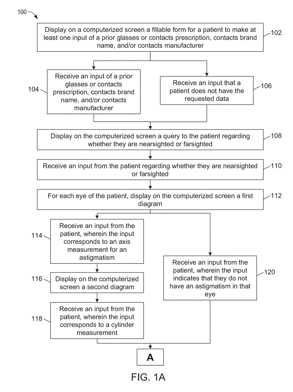
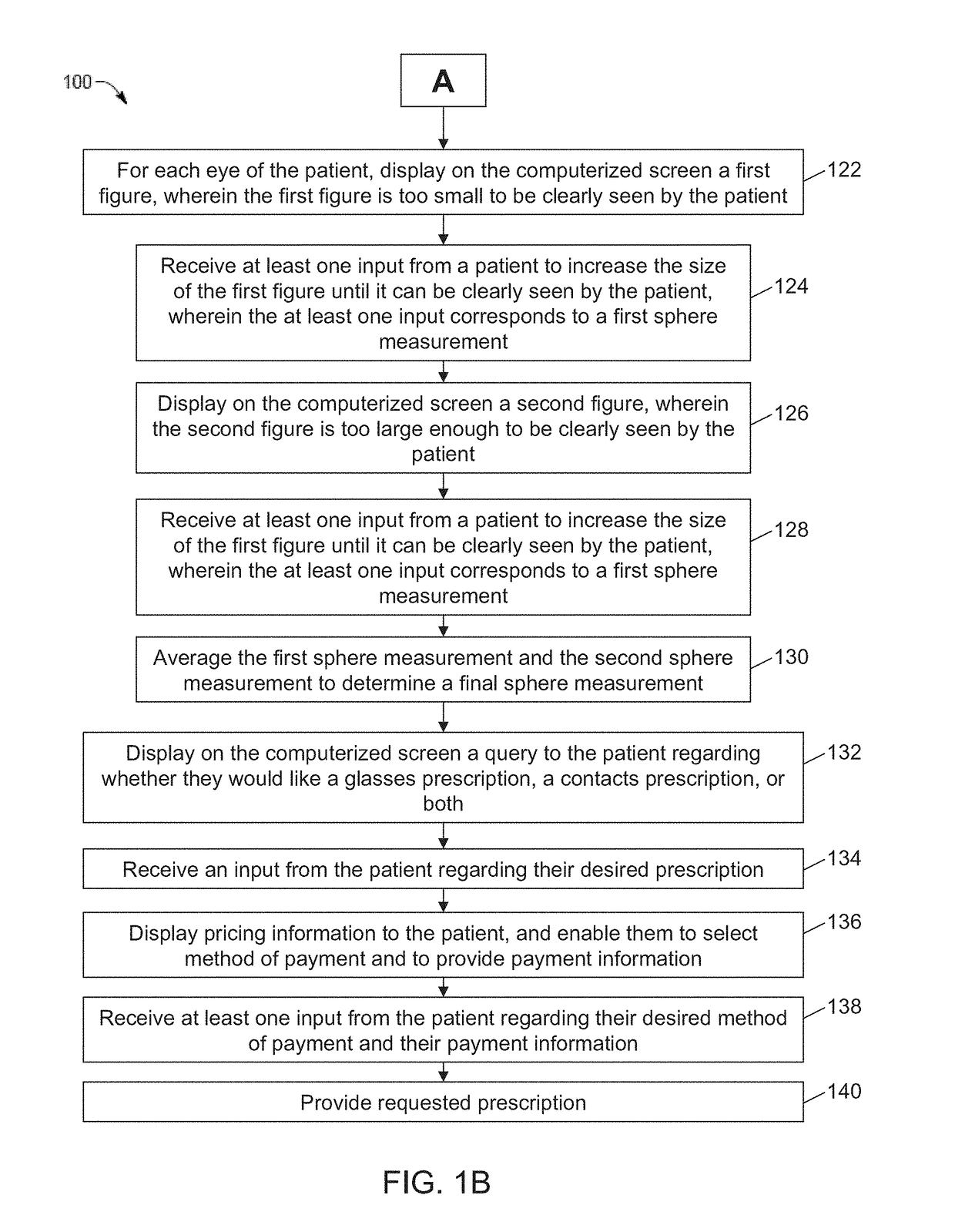
[0058]FIGS. 1A and 1B illustrate a flowchart of an example of a process or method 100 pursuant to an embodiment of the system of the present disclosure. In various embodiments, one or more processors execute a set of instructions to implement the process 100. Although process 100 is described with reference to the flowchart shown in FIGS. 1A and 1B, the system may employ many other processes of performing the acts associated with this illustrated process. For example, the system may change the order of certain of the illustrated blocks. The system can also make certain of the illustrated blocks optional, the system may repeat certain of the illustrated blocks, and / or the system may not employ certain of the illustrated blocks.

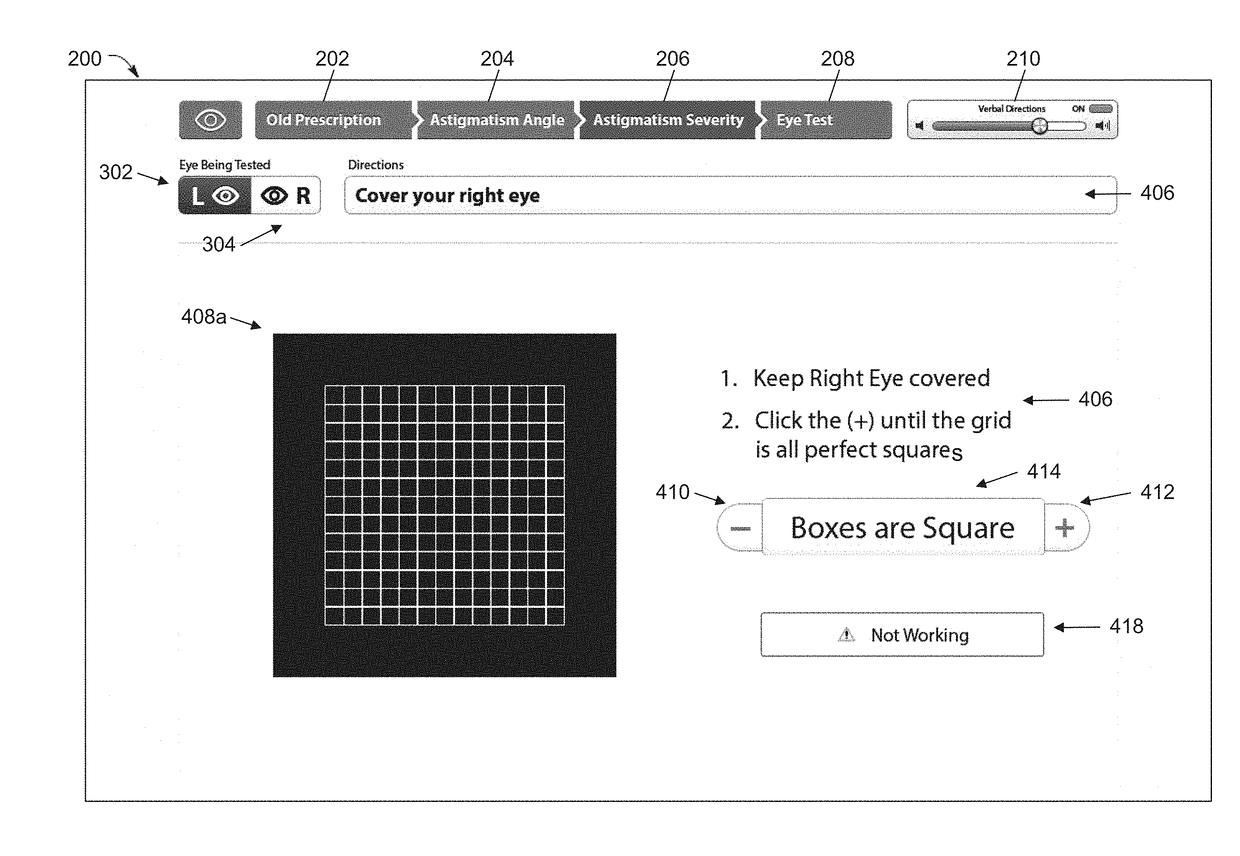
[0059]As indicated by block 102, the system displays on a computerized screen a fillable form for a patient to make at least one input of a prior glasses or contacts prescription, contacts brand name, and / or contacts manufacturer.

[0060]A computerized screen in ...


PUM


Abstract

The present disclosure relates generally to systems and method for testing and determining corrective lens prescription for a patient. In an example embodiment, a method includes using a hand-portable first electronic device, a second electronic device with a computerized screen, and a server to conduct a vision test for a person. The vision test includes determining, an axis prescription, a cylinder prescription, and a sphere prescription for each eye of the person. A corrective lens prescription is provided for the person based, at least in part, on the determined axis, cylinder, and sphere prescription for each eye of the person.

Description

PRIORITY CLAIM[0001]This non-provisional patent application is a continuation of U.S. patent application Ser. No. 15 / 468,873, tiled “COMPUTERIZED TESTING AND DETERMINATION OF A VISUAL FIELD OF A PATIENT,” filed Mar. 24, 2017, which is a continuation of U.S. patent application Ser. No. 14 / 994,949, now U.S. Pat. No. 9,603,517, titled “COMPUTERIZED PUPILLARY DISTANCE MEASUREMENT SYSTEM AND METHOD,” filed Jan. 13, 2016, which is a continuation of U.S. patent application Ser. No. 14 / 195,583, now U.S. Pat. No. 9,237,842, titled “COMPUTERIZED REFRACTION AND ASTIGMATISM DETERMINATION,” filed Mar. 3, 2014, which claims priority to and the benefit of U.S. Provisional Patent Application Ser. No. 61 / 777,481, titled “COMPUTERIZED REFRACTION,” filed on Mar. 12, 2013; U.S. Provisional Patent Application Ser. No. 61 / 864,328, titled “COMPUTERIZED REFRACTION AND ASTIGMATISM DETERMINATION,” filed Aug. 9, 2013; U.S. Provisional Patent Application Ser. No. 61 / 881,803, titled “COMPUTERIZED REFRACTION AND...

Claims


Application Information

Patent Timeline
IPC IPC(8): A61B3/032A61B5/00A61B3/18A61B3/14A61B3/11A61B3/00A61B3/036A61B3/024A61B3/107
CPCA61B3/111A61B3/036A61B3/14A61B3/107A61B3/032A61B5/0022A61B3/0058A61B3/0025A61B3/024A61B3/18A61B3/0041A61B3/02A61B3/0033A61B3/0325A61B3/1035A61B3/00A61F9/00G02C7/02A61B3/103G02C13/005
Inventor LEE, STEVEN P.
Owner VISIBLY INC
Why Eureka
Try Eureka