Check patentability & draft patents in minutes with Patsnap Eureka AI!

Novel optical interferometric scanning detector for cardiovascular function monitoring

a scanning detector and optical interferometry technology, applied in the field of portable devices, can solve the problems of affecting the accuracy of the detection method, and unable to provide complete information on the heart and blood vessels, etc., to achieve the effect of improving the tolerance to position shift, size and cos

Active Publication Date: 2018-07-12
OMNISENSING PHOTONICS LLC
View PDF1 Cites 1 Cited by
  • Summary
  • Abstract
  • Description
  • Claims
  • Application Information

AI Technical Summary

Benefits of technology

The interferometric sensing chipset is a small and cost-effective device that uses a special optical platform to measure position and movement with high accuracy. It features a built-in laser and receivers, and a scheme to guide and track the laser beam to account for any position shifts caused by human body movements. Overall, this technology offers sensitivity advantages over other methods and is easier to use and cheaper than other devices in its class.

Problems solved by technology

However, none of these methods provides complete information on both the heart and the blood vessels.
Also, there are numerous situations under which ordinary techniques are hampered, e.g., the heart sound(s) collected using an ordinary stethoscope is (are) faint or not even audible as the result of ambient noises.
Furthermore, as cardiovascular diseases need early detection of the risks, none of these methods provides early enough diagnosis unless severe events bring the patients to the hospital.
The following U.S. patents describe various prior art systems related to the above discussed problems but do not satisfy the long felt but unsolved need for portable, miniaturized multi-functional device that can perform multiple detection schemes at a minimum cost level:

Method used


Image

  • Novel optical interferometric scanning detector for cardiovascular function monitoring
  • Novel optical interferometric scanning detector for cardiovascular function monitoring
  • Novel optical interferometric scanning detector for cardiovascular function monitoring

Examples


Embodiment Construction

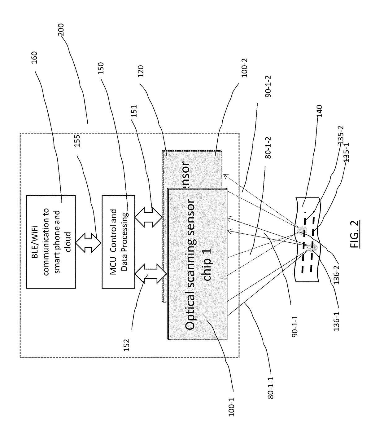
[0025]Consistent with the inventions of “Interferometric focusing beam optical cardiovascular sensor”, U.S. patent application Ser. No. 15 / 146,354 and “1D laser beam guiding and tracking system and method for interferometric focusing beam optical cardiovascular sensor”, U.S. patent application Ser. No. 15 / 235,656, this invention describes the implementation of a miniaturized handheld medical device for the cardiovascular signals monitoring purpose.

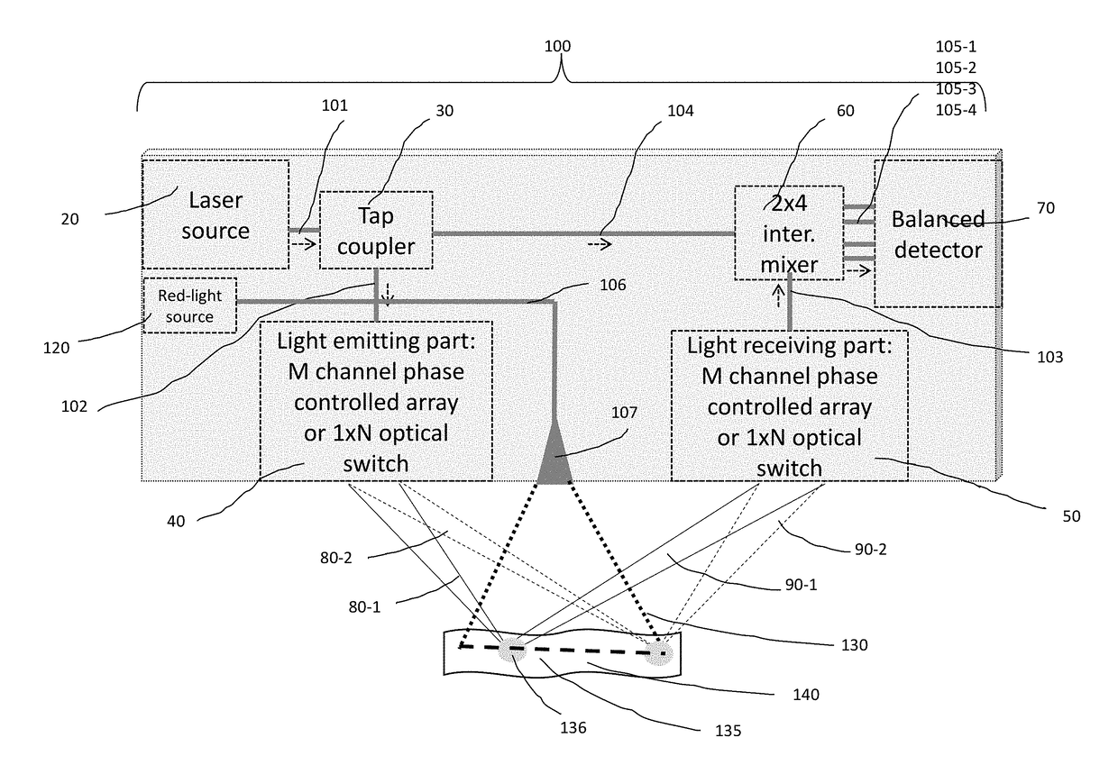
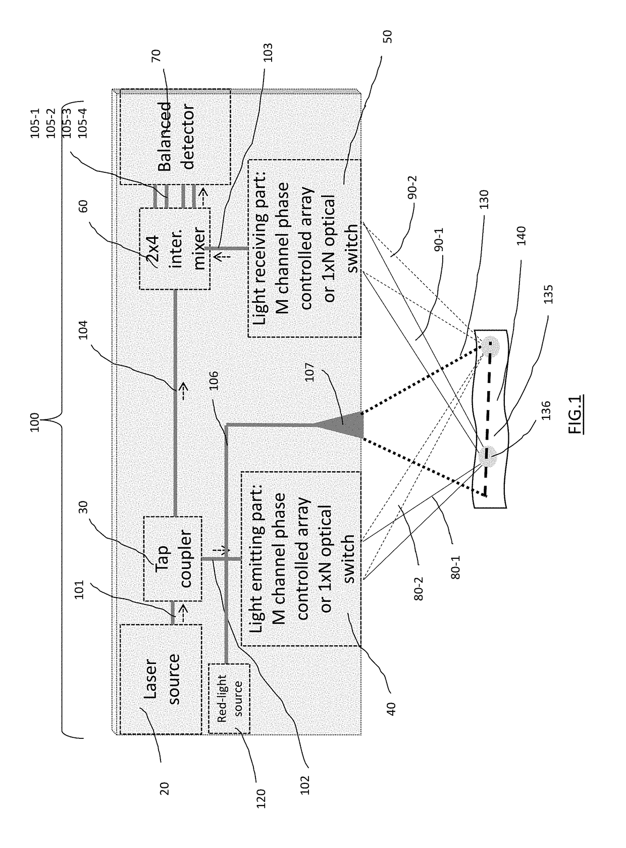
[0026]Referring to FIG. 1, this is an integrated optical waveguide chipset 100 that consists of 6 major functional parts: the laser source 20, the tap coupler 30, the light emitting part 40, the light receiving part 50, the 2×4 interferometric mixer 60 and the 2-pair balanced detectors 70. On the optical chip, laser source 20 generates the 1st laser 101. The tap coupler 30 receives the 1st laser and splits it into the 2nd laser 102 and the reference light 104. The 2nd laser 102 is received by the light emitting part 40 and converted into t...


PUM


Abstract

The object of the present invention is to disclose a novel optical miniaturized handheld medical device for convenient monitoring and / or data collection of detailed signals on human cardiovascular function. The implementation consists of a number of advanced technologies, including interferometric detection, phase controlled focusing beam steering, auto-tracking scheme and algorism, and integrated optical chip assembly to enhance the device's performance and miniaturization. Briefly, this handheld medical device directs a single or dual output laser beam(s) onto certain skin surface to detect the surface vibration velocity at the point where the laser hits the surface. The skin surface vibrates in response to cardiovascular signals, such as blood pressure pulses, turbulent blood flow through narrowed arteries, pumping actions of the heart, or the closure of the heart valves etc. The miniaturized apparatus thus is capable of detecting these signals for the assessment of cardiovascular functions in both healthy and disease conditions.

Description

CROSS-REFERENCE TO RELATED APPLICATIONS[0001]The present non-provisional application is a continuation-in-part of U.S. Non-Provisional patent application Ser. No. 15 / 146,354, filed May 4, 2016, entitled “Interferometric focusing beam optical cardiovascular sensor”, which claims priority and other benefit from U.S. Provisional Patent Application Ser. No. 62 / 174,624, filed Jun. 12, 2015, and of U.S. Non-Provisional patent application Ser. No. 15 / 235,656, filed Aug. 11, 2016, entitled “1D laser beam guiding and tracking system and method for interferometric focusing beam optical cardiovascular sensor”.BACKGROUND OF THE INVENTION[0002]The present invention relates generally to a portable apparatus that is designed as a miniaturized handheld device for cardiovascular function monitoring that can be used in either hospital or household. More specifically, the cardiovascular function monitor presented here is capable of detecting movements of skin surface due to the contraction(s) of the h...

Claims


Application Information

Patent Timeline
Patent Type & Authority Applications(United States)
IPC IPC(8): A61B5/024A61B5/00A61B5/021A61B7/04
CPCA61B5/02416A61B5/0022A61B5/742A61B7/04A61B5/02108A61B5/0064A61B5/02133A61B5/02444A61B5/1102
Inventor ZHANG, JINZHONG, SHANCHEN, WEIZHU, ZHONGHUAWU, LEI
Owner OMNISENSING PHOTONICS LLC
Features
  • R&D
  • Intellectual Property
  • Life Sciences
  • Materials
  • Tech Scout
  • Unparalleled Data Quality
  • Higher Quality Content
  • 60% Fewer Hallucinations
Learn More