Locking mechanism for locking a floating platform loaded with a machine onto a base, shock absorbing device with locking mechanism, and method thereof

Active Publication Date: 2018-07-12
WISTRON CORP
View PDF21 Cites 2 Cited by
  • Summary
  • Abstract
  • Description
  • Claims
  • Application Information

AI Technical Summary

Benefits of technology

The patent is about a shock absorbing device used to transport and install machines. It has a simple structure and is easy to operate. The device uses engagement and disengagement of first and third fixing components to restrain the movement of the platform relative to the base. This prevents the machine from vibrating or being damaged during transportation. When the machine reaches the destination, the device can be easily released to absorb shock loads during operation, protecting the machine from impact.

Problems solved by technology

Shock loads during operation may affect light paths of optical components inside the medical apparatus and reduce precision of detection.
However, shock loads during transportation are much greater than the shock loads during operation.
Therefore, the dampers cannot effectively absorb the shock loads during transportation but amplify the shock loads during transportation, so that internal components of the machine may be displaced from originals positions and damaged due to collision.
Besides, after the machine arrives at destination, it has to calibrate the machine again or replace damaged components, which increases manufacturing cost.

Method used


Image

  • Locking mechanism for locking a floating platform loaded with a machine onto a base, shock absorbing device with locking mechanism, and method thereof
  • Locking mechanism for locking a floating platform loaded with a machine onto a base, shock absorbing device with locking mechanism, and method thereof
  • Locking mechanism for locking a floating platform loaded with a machine onto a base, shock absorbing device with locking mechanism, and method thereof

Examples


Embodiment Construction

[0023]In the following detailed description of the preferred embodiments, reference is made to the accompanying drawings which form a part hereof, and in which is shown by way of illustration specific embodiments in which the disclosure may be practiced. In this regard, directional terminology, such as “top,”“bottom,”“front,”“back,” etc., is used with reference to the orientation of the Figure(s) being described. The components of the present disclosure can be positioned in a number of different orientations. As such, the directional terminology is used for purposes of illustration and is in no way limiting. Accordingly, the drawings and descriptions will be regarded as illustrative in nature and not as restrictive.

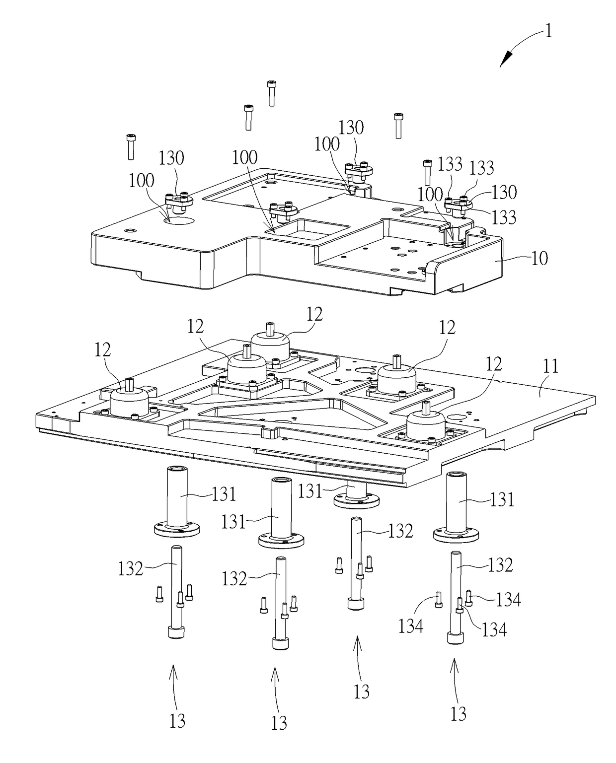
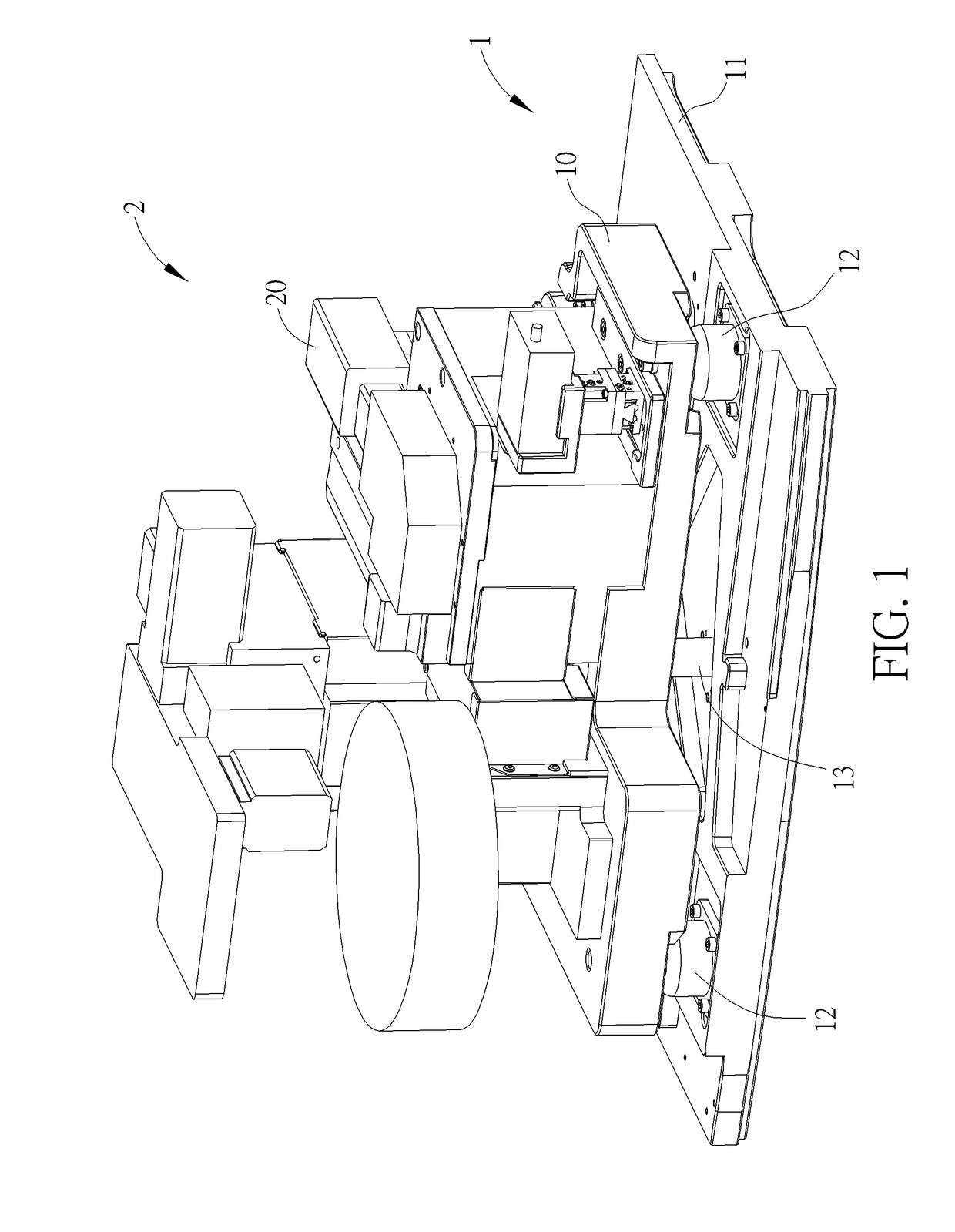
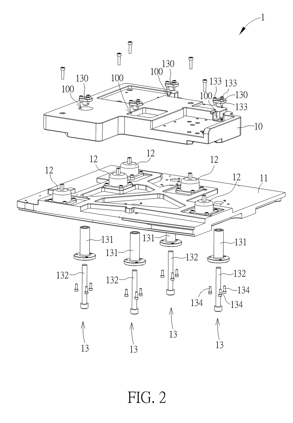
[0024]Please refer to FIG. 1 to FIG. 3. FIG. 1 is a schematic diagram of a shock absorbing device 1 according to an embodiment of the present disclosure. FIG. 2 is an exploded diagram of the shock absorbing device 1 according to the embodiment of the present disclosure. F...


PUM


Abstract

A shock absorbing device includes a floating platform, a base, and at least three locking mechanisms. The floating platform is movably spaced above the base and loaded with a machine. A center of gravity of the floating platform and the machine is located within a field enclosed by the at least three locking mechanisms. Each of the at least three locking mechanisms includes a first fixing component, a second fixing component, and a third fixing component. The first fixing component is disposed on the floating platform. The second fixing component is disposed on the base and located at a position corresponding to the first fixing component. The third fixing component is disposed on the second fixing component to engage with the first fixing component, so that the floating platform can be locked onto the base, which prevents damage of internal components of the machine caused by shock loads during transportation.

Description

BACKGROUND OF THE INVENTION1. Field of the Invention[0001]The present disclosure relates to a locking mechanism and a shock absorbing device, and more particularly, to a locking mechanism for locking a floating platform loaded with a machine onto a base, a shock absorbing device with the locking mechanism, and a method thereof.2. Description of the Prior Art[0002]With advance of technology, requirement for precision of a machine, especially for a medical apparatus, becomes higher. Shock loads during operation may affect light paths of optical components inside the medical apparatus and reduce precision of detection. In order to prevent the precision of detection from being affected by the shock loads during operation, some machines are equipped with dampers for absorbing shock loads during operation. The dampers and the machines are usually assembled and calibrated in advance before transportation for reducing manufacturing cost. However, shock loads during transportation are much g...

Claims


Application Information

Patent Timeline
IPC IPC(8): B65B55/20E04F15/22E04F15/18E04F15/02E04B1/98
CPCB65B55/20E04F15/225E04F15/18B23Q1/0054E04B1/98E01C2301/40B64D9/003E04F15/02194F16B1/00F16F15/02F16F15/04
Inventor LI, CHUAN-SHENG
Owner WISTRON CORP
Why Eureka
Try Eureka