Gas turbine guide vane segment and method of manufacturing

Active Publication Date: 2018-07-12
SIEMENS ENERGY GLOBAL GMBH & CO KG
View PDF39 Cites 4 Cited by
  • Summary
  • Abstract
  • Description
  • Claims
  • Application Information

AI Technical Summary

Benefits of technology

[0011]The present invention seeks to mitigat

Problems solved by technology

In such a casting process there is a limitation in geometry and in providing cooling features, as not all possible configurations can be produced.
Casting of guide vane segments can be ver

Method used


Image

  • Gas turbine guide vane segment and method of manufacturing
  • Gas turbine guide vane segment and method of manufacturing
  • Gas turbine guide vane segment and method of manufacturing

Examples


Embodiment Construction

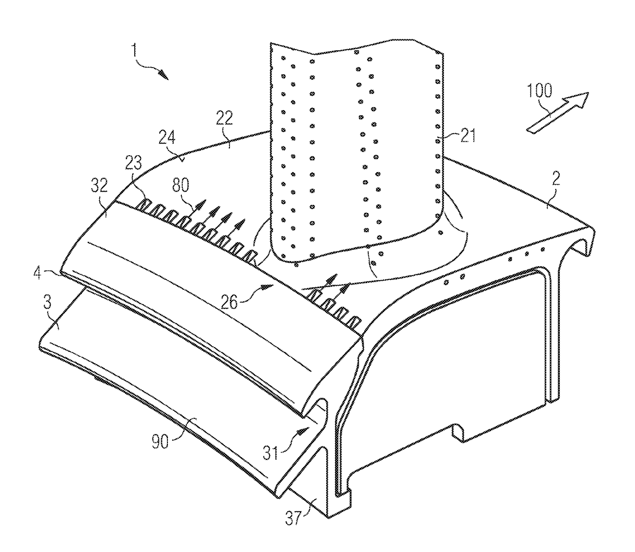
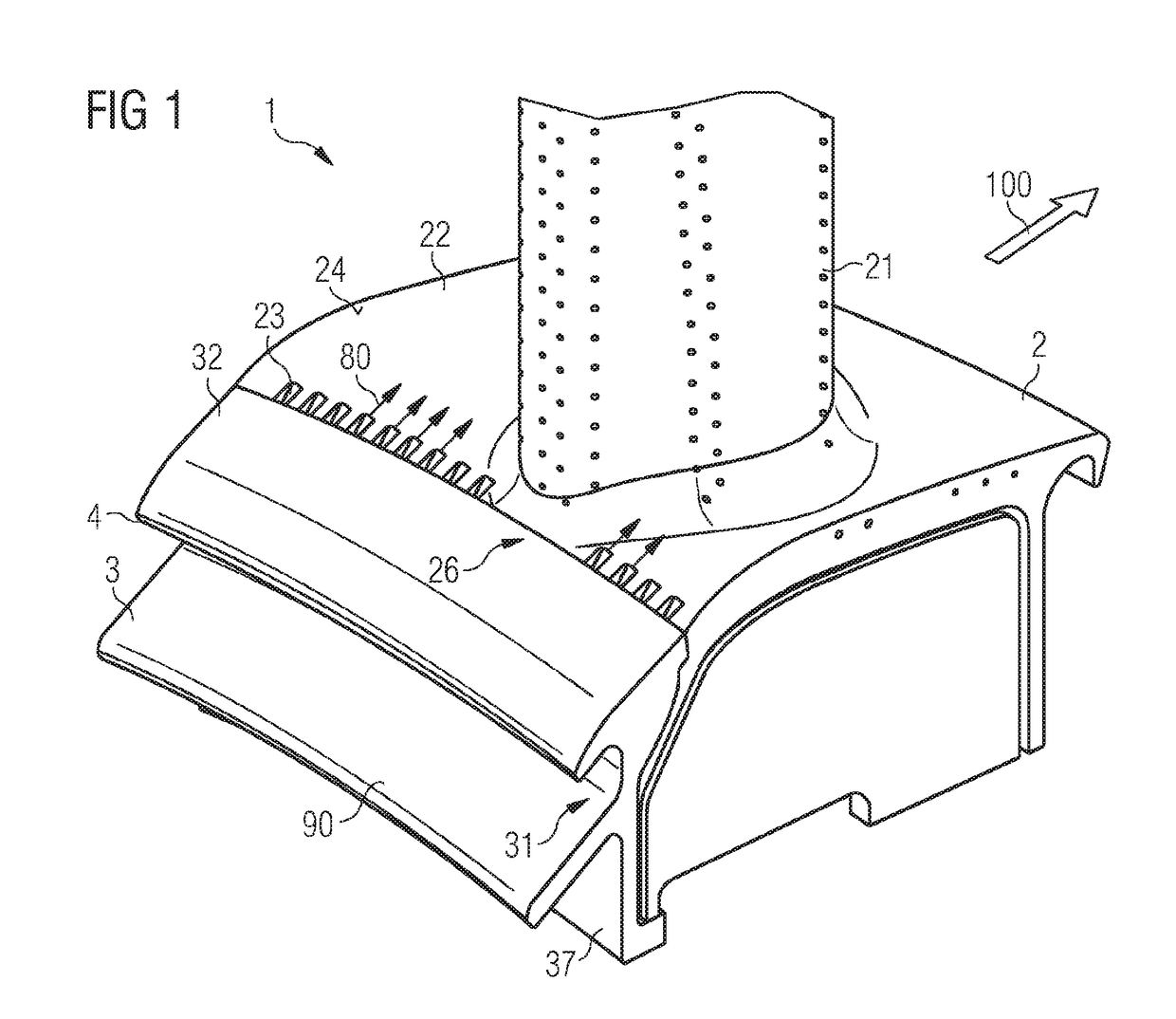
[0046]FIG. 1 shows a gas turbine gas vane segment 1 consisting of two separately manufactured parts. These parts are the first guide vane part 2 and the second guide vane part 3. A plurality of these gas turbine guide vane segments 1 generate a full ring for a turbine stage within a gas turbine engine. The first guide vane part 2 comprises an aerofoil 21 and a first platform section 22. The aerofoil 21 will extend into a working fluid path of the turbine section of the gas turbine engine. The first platform section 22 is a segment of a boundary wall for that working fluid flow during operation, i.e. a working fluid washed surface. The working fluid is the output of an upstream combustor and is typically a hot gas.

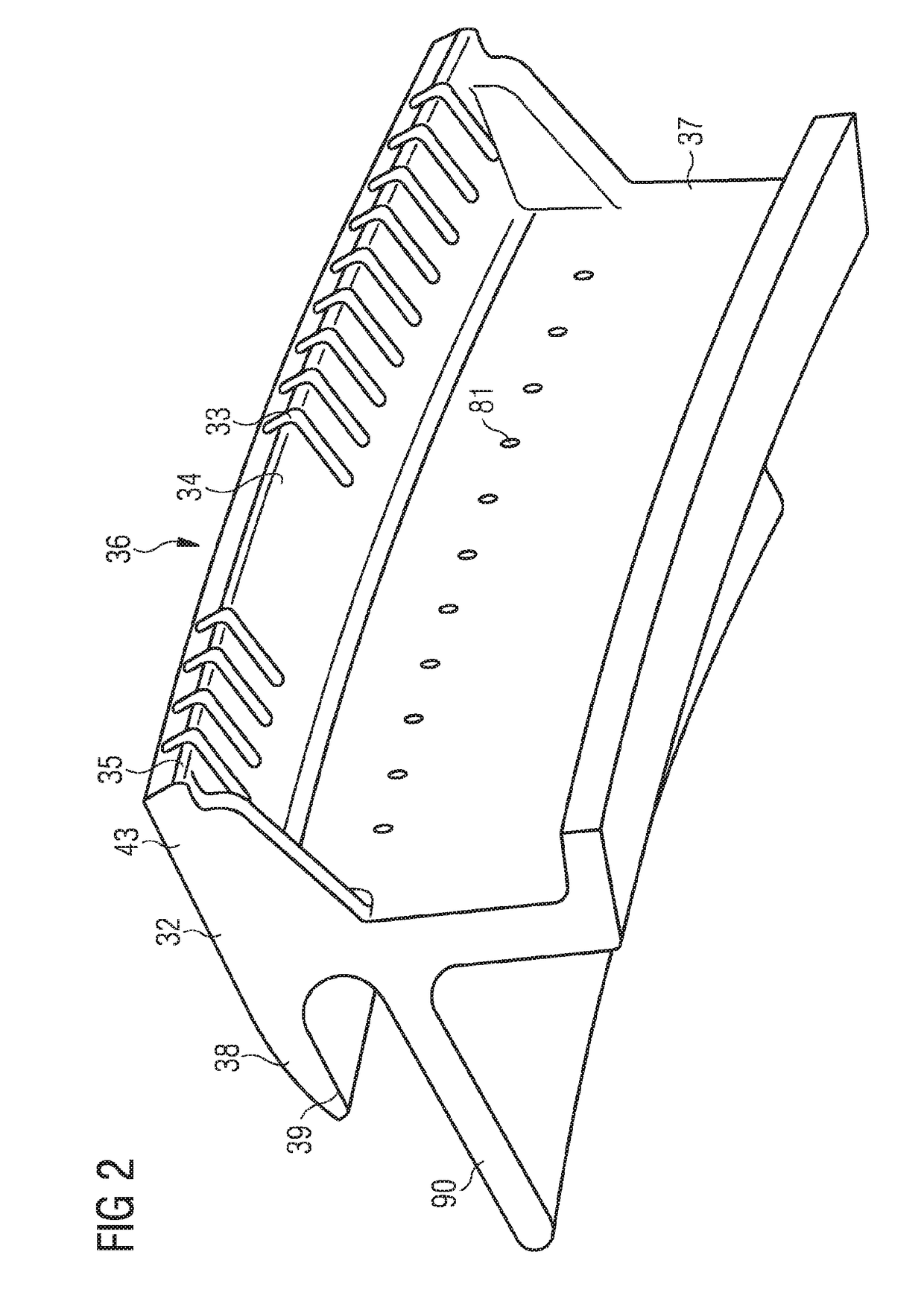
[0047]The second guide vane part 3 shows a geometry of an upstream end of the gas turbine guide vane segment 1. Particularly the second guide vane part 3 comprises a second platform section 32 and a seal section 31. The second platform section 32, like the first platform se...


PUM


Abstract

A gas turbine guide vane segment has a first guide vane part with an aerofoil and a first platform section and a second guide vane part with a second platform section. The first guide vane part and the second guide vane part are separately manufactured parts joined together such that the second platform section defines a leading edge of the gas turbine guide vane segment and such that the first platform section and the second platform section form an aligned common platform surface of the gas turbine guide vane segment. The first platform section includes slots in the first platform section for guiding cooling fluid along a surface of the first platform section for film cooling of the surface, the slots being provided at an upstream bend of the first platform section and the slots are provided on a side of the first platform section facing the working fluid.

Description

CROSS REFERENCE TO RELATED APPLICATIONS[0001]This application is the US National Stage of International Application No. PCT / EP2016 / 067109 filed Jul. 19, 2016, and claims the benefit thereof. The International Application claims the benefit of European Application No. EP15185103 filed Sep. 14, 2015. All of the applications are incorporated by reference herein in their entirety.FIELD OF THE INVENTION[0002]The invention relates to a gas turbine guide vane segment built from two separate parts and consecutively joined.BACKGROUND OF THE INVENTION[0003]Gas turbine engines mainly comprise a compressor section, a combustor section, and a turbine section. The turbine section itself again is comprised of a plurality of turbine stages. Each turbine stage consists of a set of guide vanes followed by a set of rotor blades. The guide vanes and the rotor blade experience high temperatures during operation and therefore are manufactured from high temperature resistant material and / or require coolin...

Claims


Application Information

Patent Timeline
IPC IPC(8): F01D9/04F01D11/02F01D5/18
CPCF01D9/041F01D11/02F01D5/186F05D2240/121F05D2230/211F05D2230/237F05D2240/81
Inventor GRANBERG, PERSZIJARTO, JANOS
Owner SIEMENS ENERGY GLOBAL GMBH & CO KG
Why Eureka
Try Eureka