
Linear actuator

Active Publication Date: 2018-07-12
METROL SPRINGS
View PDF1 Cites 1 Cited by
  • Summary
  • Abstract
  • Description
  • Claims
  • Application Information

AI Technical Summary

Benefits of technology

The patent describes a valve that prevents fluid from flowing through the valve when the cylinder and base are not connected. The valve automatically opens when the parts are disengaged, allowing fluid to flow through. The technical effect of this design is to ensure the proper flow of fluid through the valve and to prevent leakage when the parts are not connected.

Problems solved by technology

Although such conventional press cushions are generally effective, they incur certain practical disadvantages, and so in certain applications it may be desirable to replace such a press cushion with an array of gas springs.
However, whilst the function of conventional gas springs is satisfactory for use in substitute of a press cushion, their construction does not lend itself so readily to such a use.
In particular, problems are encountered using gas springs in substitute of a press cushion on a pressing machine used for multiple different pressings where different blank-holder force distribution patterns are required.
However, in such a use of gas springs a problem is encountered inasmuch that, following pressing of a first part, to re-purpose the pressing machine for pressing of a differently shaped part requiring a different distribution of blank-holder force, it is necessary to reconfigure the gas springs, by unbolting the gas springs from their original position and reattaching them to the bed at a new position, and subsequently reconfiguring the gas supply pipes.
It will be appreciated that this method of repositioning gas springs incurs significant time costs and can result in an (often expensive) pressing machine standing redundant whilst an operative reconfigures the gas spring array.

Method used


Image

  • Linear actuator
  • Linear actuator
  • Linear actuator

Examples


Embodiment Construction

FIG. 1

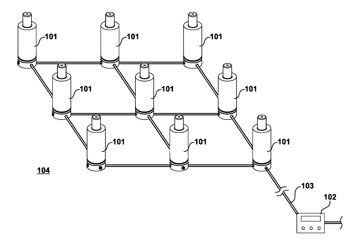
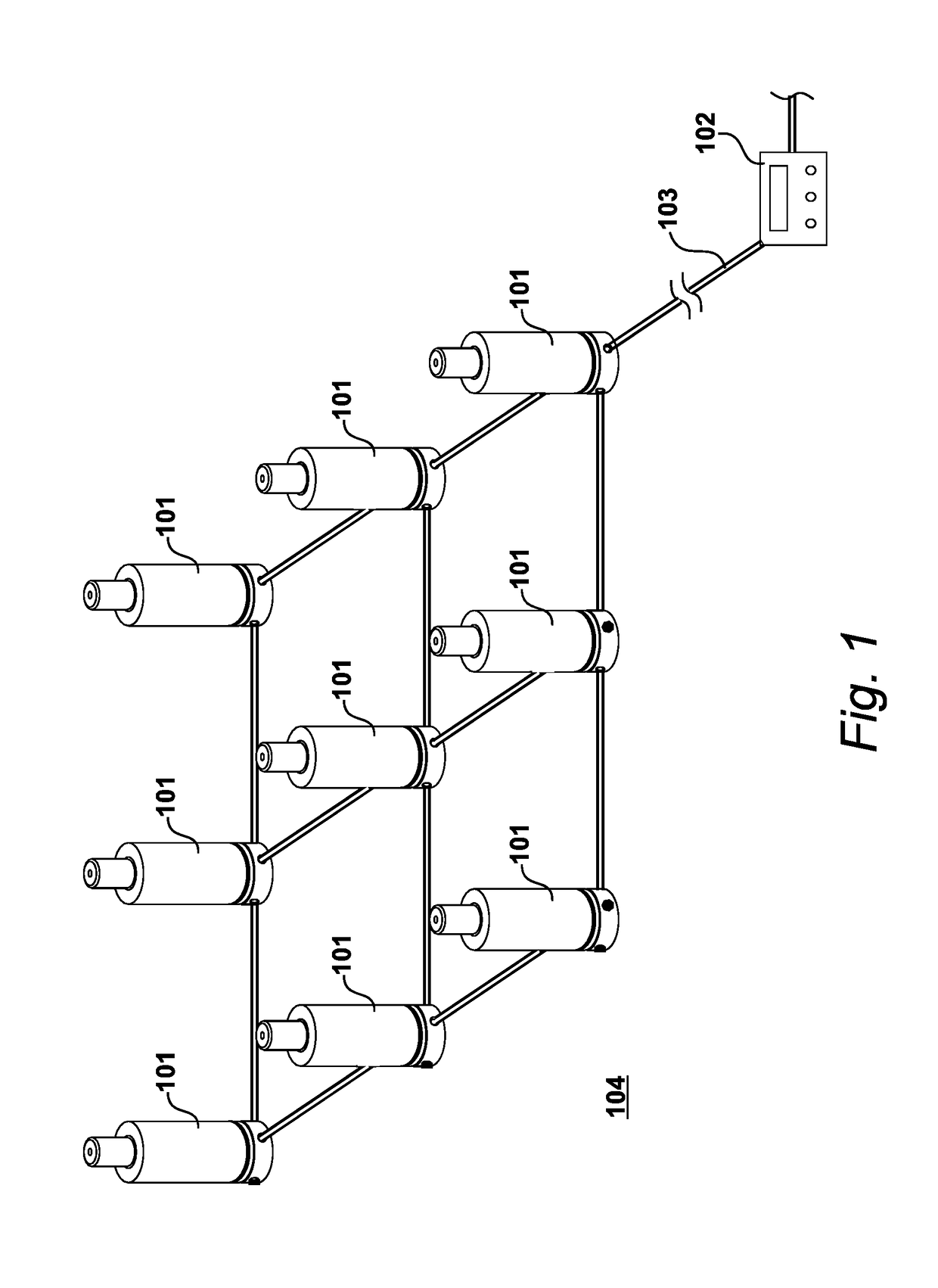
[0037]An example of an environment in which the present invention can be used is shown in FIG. 1.

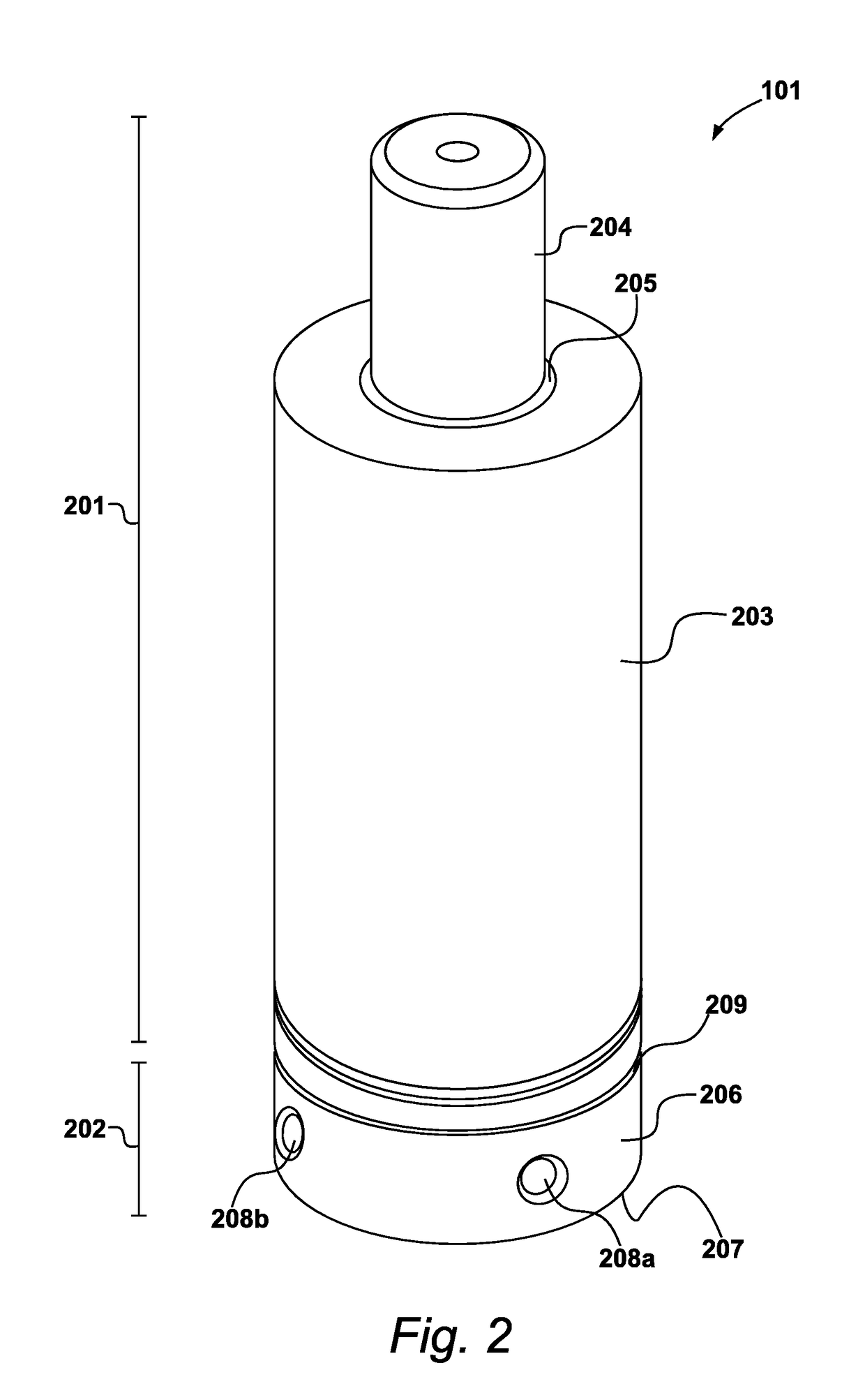
[0038]Aspects of the present invention relate to an improved construction of a linear actuator. The term linear actuator as used herein includes both hydraulic and pneumatic cylinders. A specific embodiment of the invention described herein in detail is a pneumatic cylinder. More particularly, the specific embodiment of the invention described herein is a pneumatic cylinder configured as a ‘gas spring’. As will be understood, a gas spring is a type of spring that, unlike a typical metal spring, uses a compressed gas, contained in a cylinder and compressed by a piston, to exert a force.

[0039]One use for such a gas spring that is of particular interest to the present applicant is a gas spring for supporting a blank-holder in a metal-pressing machine. Thus, in the specific embodiment described herein, the gas spring is a gas spring suitable for exerting a force on a blank-holder resti...


PUM

PropertyMeasurementUnit
Flow rateaaaaaaaaaa
Widthaaaaaaaaaa
Hardnessaaaaaaaaaa

Abstract

A linear actuator is disclosed. The linear actuator comprises a cylinder portion and a base portion. The cylinder portion comprises a housing defining internally a compression chamber for containing a fluid and comprising a piston assembly that can reciprocate within the compression chamber. The housing further defines a cylinder port in fluid communication with said compression chamber. The base portion defines a first base port and a second base port and a passage extending therebetween fluidly communicating the first base port with the second base port, and comprises valve means operable to control the flow of fluid through the second base port, in which the valve means is actuatable between an open condition in which the flow of fluid through the second base port is permitted, and a closed condition in which the flow of fluid through the second base port is substantially prevented. The cylinder portion is releasably engageable with the base portion such that the cylinder portion and the base portion may be arranged in an engaged condition in which engaged condition the cylinder port and the second base port are in fluid communication.

Description

CROSS REFERENCE TO RELATED APPLICATIONS[0001]This application claims priority from United Kingdom patent application No. 17 00 561.2 filed 12 Jan. 2017, the whole contents of which are incorporated herein by reference in their entirety.BACKGROUND OF THE INVENTION1. Field of the Invention[0002]The present invention relates to linear actuators, and in particular to linear actuators in the form of pneumatic cylinders. More particularly, the present invention relates to gas springs.2. Description of the Related Art[0003]Linear actuators are mechanisms that produce linear forces. Linear actuators have utility in a wide range of applications, notably in industrial machinery, for automated movement of components of the machinery or for damping such components. Two types of linear actuator of particular interest are hydraulic cylinders and pneumatic cylinders. Hydraulic and pneumatic cylinders use a working fluid, in the case of a hydraulic cylinder typically a hydraulic oil and in the case...

Claims


Application Information

Patent Timeline
IPC IPC(8): F15B15/14F16F9/02B30B1/34B30B1/38
CPCF15B15/1428F15B15/1452F16F9/0281B30B1/34B30B1/38F16F9/325F16F9/3242B21D24/14F16F15/0232B30B15/06F15B15/00F16F9/02
Inventor PEGRAM, CHRISTOPHER JOHNHYNES, PAUL TERENCE
Owner METROL SPRINGS
Learn More