LED spot with customizable beam shape, beam color and color uniformity

US20180195684A1Active Publication Date: 2018-07-12SIGNIFY HLDG BV

Image

  • LED spot with customizable beam shape, beam color and color uniformity
  • LED spot with customizable beam shape, beam color and color uniformity
  • LED spot with customizable beam shape, beam color and color uniformity

Examples


Embodiment Construction

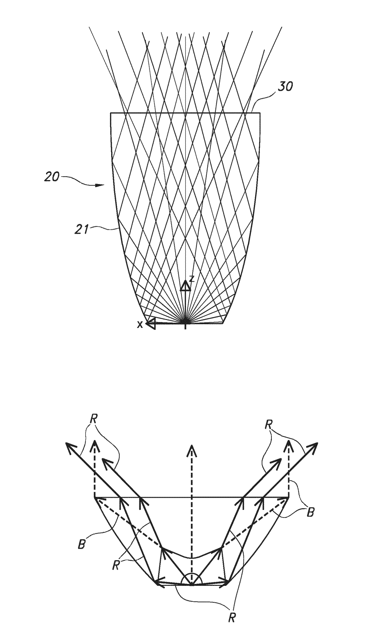
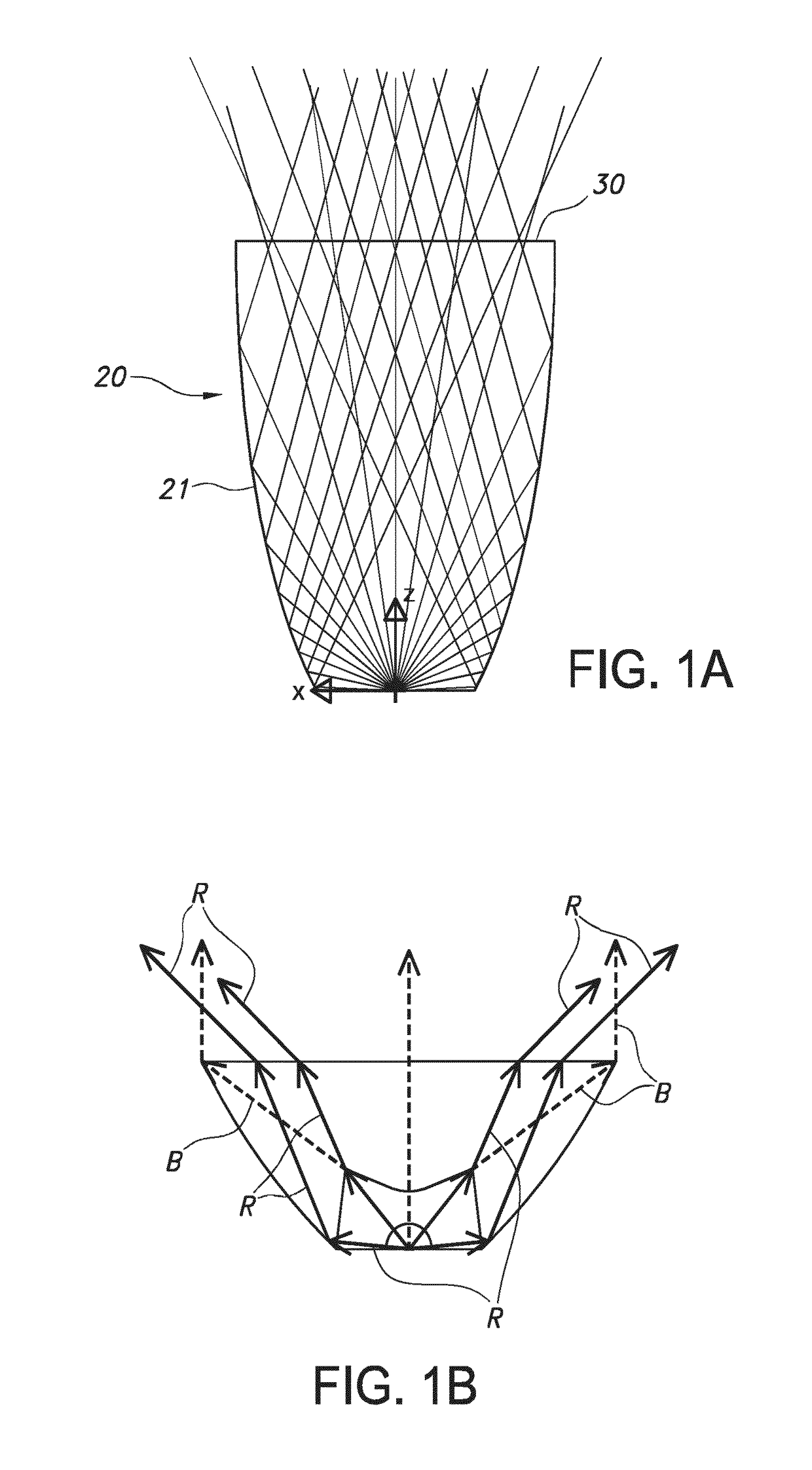
[0039]To clarify the effect of the invention, light ray trajectories for several optical elements were calculated.

[0040]In a first example, see FIG. 1a, a CPC (compound parabolic concentrator) is used as a reflector 21. In this type of beam shaping optics 20, the etendue is conserved. As a result, the full exit window, indicated with Ref. 30, is utilized for all light directions, i.e. the exit is fully flashed for all viewing directions within the beam. The present invention, which proposes to shape the beam by applying a mask at the exit window, is substantially not function with such etendue-conserving collimator. The present invention is especially directed to beam modifying of beams due to non-imaging optics that are not completely etendue conserving, i.e. the exit window is not fully flashed in all viewing directions within the beam. Hence, the optics used are especially not completely etendue conserving, i.e. only partly etendue conserving. Especially, the exit window is not f...


PUM


Abstract

The invention provides a lighting unit (1000) comprising a lighting device (100), wherein the lighting device (100) comprises a light source (10) configured to provide light source light (11) and beam shaping optics (20) configured to shape the light source light into a lighting device beam (101), wherein the lighting device (100) comprises a window (30) comprising an upstream face (31) directed to the light source (10) and a downstream face (32), wherein the lighting unit (1000) further comprises a beam modifier (200) configured adjacent to the window (30) and configured to intercept at least part of said lighting device beam (101), wherein the lighting device (100) and the beam modifier (200) are configured to modify said lighting device beam (101) to provide a lighting unit beam (1001) downstream from said beam modifier (200), wherein the beam modifier (200) comprises a printed beam modifying element (210).

Description

FIELD OF THE INVENTION[0001]The invention relates to a lighting unit as well as a kit of parts comprising a lighting device and a beam modifier. The invention also relates to a method of making such lighting unit.BACKGROUND OF THE INVENTION[0002]The desire to modify beam characteristics is known in the art. US2013058099, for instance, describes an illumination source configured to output light having a user-modifiable beam characteristic which includes a LED light unit for providing a light output in response to an output driving voltage, a driving module for receiving an input driving voltage for providing the output driving voltage to the LED light unit, a heat sink coupled to the LED light unit for dissipating heat produced by the LED light unit and the driving module, a reflector coupled to the heat sink for receiving the light output, for outputting a light beam having a first beam characteristic, and a lens coupled to the heat sink for receiving the light beam having the first...

Claims


Application Information

Patent Timeline
12 Jul 2018
Publication
US20180195684A1
IPC
F21V7/00
CPC
F21V7/0091; F21Y2115/00; B33Y80/00; F21K9/233; F21V3/04; F21V5/045; F21V9/00; F21V11/16
Inventors
VISSENBERG, MICHEL CORNELIS JOSEPHUS MARIE; TALGORN, ELISE CLAUDE VALENTINE