Winding and scale configuration for inductive position encoder

Active Publication Date: 2018-07-12
MITUTOYO CORP
View PDF0 Cites 17 Cited by
  • Summary
  • Abstract
  • Description
  • Claims
  • Application Information

AI Technical Summary

Benefits of technology

[0028]The most basic combinations of design features disclosed above are sufficient to eliminate certain design constraints that have been taken for granted in the prior art (e.g., in the '958 patent) as being necessary design constraints in order to compensate or neutralize certain “offset” signal components in inductive encoders. As one example, the '958 patent requires an unconventional scale that is not widely available (that is, a scale having two parallel tracks wherein the scale pattern is offset by one half of its scale pitch, relative to one another). Such a scale carries a cost and availability penalty, and is not compatible with other types of detectors. Advantageously, either unconventional or conventional scales may be used with various corresponding embodiments disclosed herein. As another example, the prior art (e.g., the '958 patent), assumes or requires perfect symmetry in the two symmetric halves of the detector portion that align along two parallel scale tracks. However, this fails to consider that layout and routing asymmetries may arise due to practical layout, fabrication or manufacturing constraints, which will lead to various signal asymmetries and prevent “signal offset” neutralization from being achieved. This is particularly true considering that multiple “spatial phase” coil configurations must be superimposed in the same area, in contrast to the si

Problems solved by technology

Magnetic and inductive transducers are relatively robust to contamination, but not perfectly so.
However, the '958 patent requires an unconventional scale, and shows only schematic coil layouts.
In contrast, it fails to consider and/or solve certain fabrication problems and/or limitations that typically result in “non-ideal” sensors

Method used


Image

  • Winding and scale configuration for inductive position encoder
  • Winding and scale configuration for inductive position encoder
  • Winding and scale configuration for inductive position encoder

Examples


Embodiment Construction

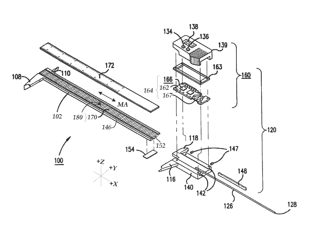
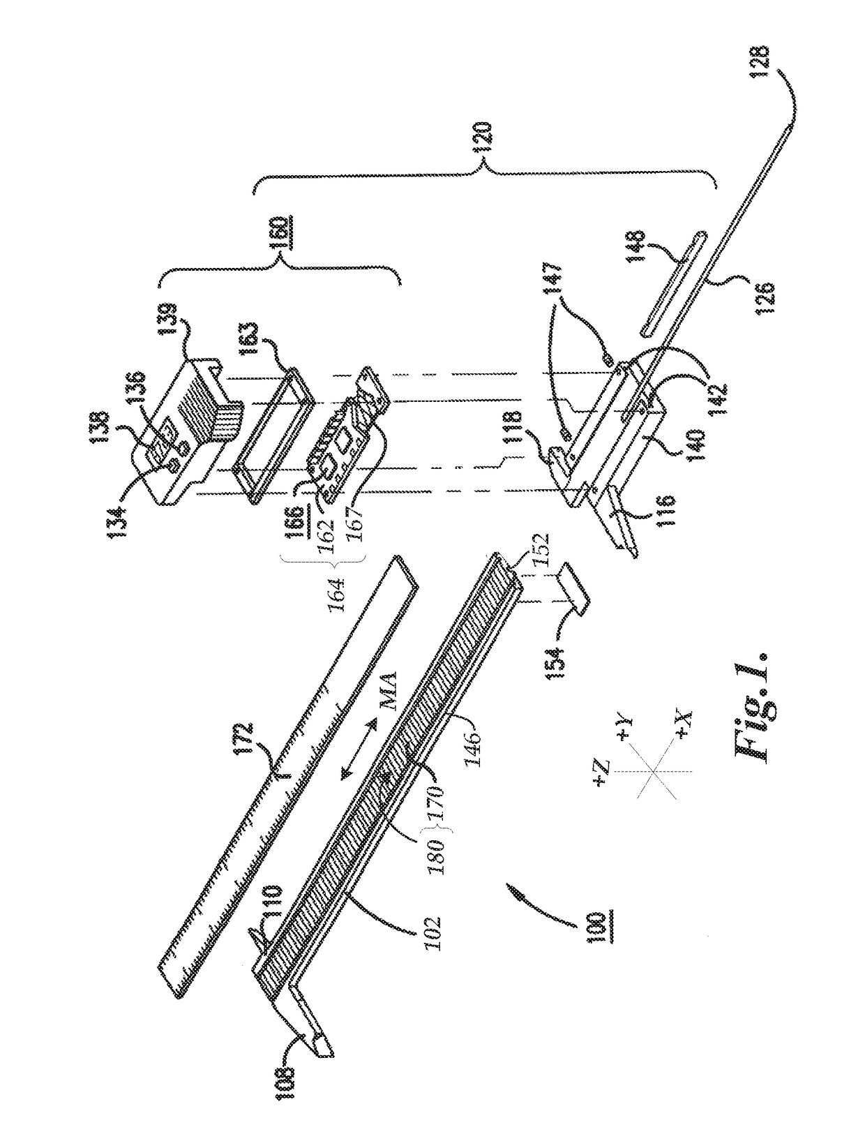
[0043]FIG. 1 is an exploded isometric view diagram of a hand tool type caliper 100 including a scale member 102 having a spar of roughly rectangular cross-section including a scale 170, and slider assembly 120. In various implementations, the scale 170 may extend along the measuring axis direction MA (e.g., corresponding to an x-axis direction) and may include a signal modulating scale pattern 180. A known type of cover layer 172 (e.g., 100 μm thick) may cover the scale 170. Jaws 108 and 110 near a first end of the scale member 102 and movable jaws 116 and 118 on the slider assembly 120 are used to measure dimensions of objects in a known manner. The slider assembly 120 may optionally include a depth bar 126, restrained in a depth bar groove 152 under the scale member 102, by an end stop 154. The depth bar engagement end 128 may extend into a hole to measure its depth. A cover 139 of the slider assembly 120 may include an on / off switch 134, a zero-setting switch 136 and a measuremen...


PUM


Abstract

A pitch compensated inductive position encoder includes a scale comprising first and second tracks including periodic patterns having a wavelength W, a detector, and signal processing. The second track pattern may be shifted along the measuring direction by a pattern offset STO relative to the first track pattern. In the detector, first-track and second-track field generating coil portions generate fields in first and second interior areas aligned with the first and second pattern tracks, respectively. First and second sensing coil configurations that are aligned with the first and second tracks, respectively, are offset relative to one another by STO+/−0.5*W along the measuring direction. In various embodiments, the first and second sensing coil configurations may have the same sequence of individual coil polarities if the generated field polarities are different, and may have inverted or opposite sequences if the generated field polarities are the same.

Description

CROSS-REFERENCE TO RELATED APPLICATION(S)[0001]This application is a continuation-in-part of U.S. patent application Ser. No. 15 / 850,457, entitled “WINDING AND SCALE CONFIGURATION FOR INDUCTIVE POSITION ENCODER”, filed Dec. 21, 2017, which is a continuation-in-part of U.S. patent application Ser. No. 15 / 245,560, entitled “WINDING CONFIGURATION FOR INDUCTIVE POSITION ENCODER,” filed Aug. 24, 2016, the disclosures of which are each hereby incorporated herein by reference in their entirety.BACKGROUNDTechnical Field[0002]This disclosure relates to measurement instruments, and more particularly to inductive position encoders that may be utilized in precision measurement instruments.Description of the Related Art[0003]Various encoder configurations may include various types of optical, capacitive, magnetic, inductive, movement and / or position transducers. These transducers use various geometric configurations of a transmitter and a receiver in a read head to measure movement between the r...

Claims


Application Information

Patent Timeline
IPC IPC(8): G01D5/20G01B7/02G01B7/00G01B3/00
CPCG01D5/2053G01B7/023G01B7/003G01B3/004G01B3/205
Inventor COOK, TED STATON
Owner MITUTOYO CORP
Why Eureka
Try Eureka