Shutter apparatus and image capturing apparatus

a technology of shutter and shutter blade, applied in shutters, optics, cameras, etc., can solve the problems of long release time lag, large power consumption amount, and inability to obtain the curtain speed necessary for a high shutter speed, and achieve the effect of reducing power consumption amount and shortening release time lag

Active Publication Date: 2018-07-12
CANON KK
View PDF2 Cites 3 Cited by
  • Summary
  • Abstract
  • Description
  • Claims
  • Application Information

AI Technical Summary

Benefits of technology

[0004]This embodiment provides a shutter apparatus and an image capturing apparat

Problems solved by technology

However, the shutter apparatus disclosed in JP 7-56211 cannot sufficiently accelerate the driving ring in the acceleration area depending on the output of the motor to be used and may not obtain a curtain speed necessary for a high shutter speed.
This shutter apparatus can accelerate the curtain speed

Method used


Image

  • Shutter apparatus and image capturing apparatus
  • Shutter apparatus and image capturing apparatus
  • Shutter apparatus and image capturing apparatus

Examples


first embodiment

[0032]Referring now to FIG. 8, a description will be given of an image capturing apparatus according to a first embodiment of the present invention. FIG. 8 is a block diagram of an image capturing apparatus 400. In FIG. 8, reference numeral 401 denotes an image capturing lens, reference numeral 113 denotes a focal plane shutter (shutter apparatus), reference numeral 403 denotes an image sensor, reference numeral 481 denotes a mirror member, and reference numeral 482 denotes a finder apparatus. When the image capturing apparatus 400 is in the finder observation state as illustrated in FIG. 8, part of a light flux in object light that has passed the image capturing lens 401 is reflected on the mirror member 481 located on the image capturing optical path, and guided to the finder apparatus 482. Thereby, the photographer can observe the object image via the finder apparatus 482. When the finder observation state turns into an image capturing state or a live-view state, the mirror membe...

second embodiment

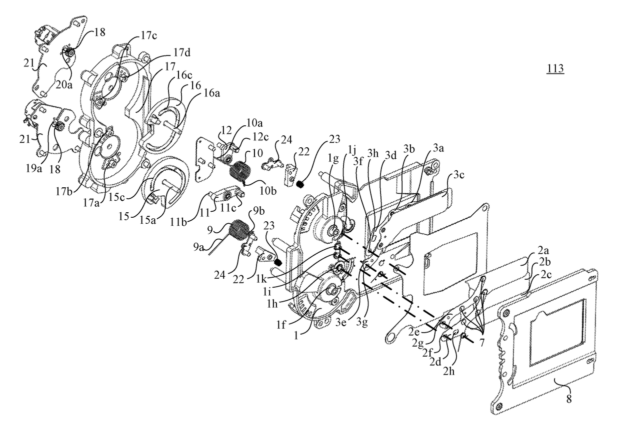
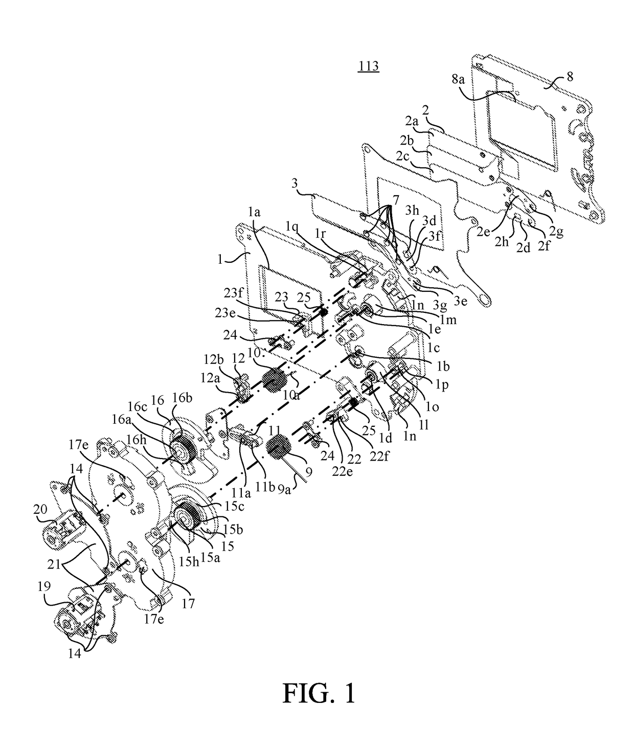
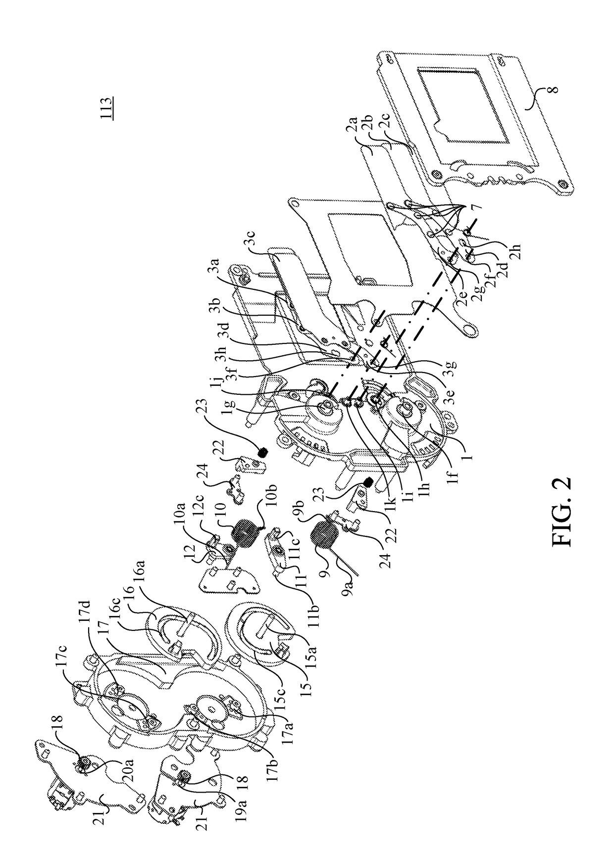
[0075]Next follows a description of the image capturing apparatus according to a second embodiment of the present invention. Referring now to FIGS. 9 to 13, a description will be given of the configuration of the focal plane shutter 113 according to this embodiment. FIG. 9 is an exploded perspective view of the focal plane shutter 113a according to this embodiment viewed from the object side. FIG. 10 is an exploded perspective view of the focal plane shutter 113a viewed from the image sensor 403 side. FIG. 11 is a front view of a first cam gear 65 and a second cam gear 66 (cam members) viewed from the object side. FIGS. 12A and 12B are perspective views of a first drive member 61 and a second drive member 62. FIG. 13 is a front view of a first assist gear 63 and a second assist gear (transmission members) viewed from the object side.

[0076]A cover plate 58 is attached to a shutter base plate 51 on the object side. A first blade unit that includes blades 52a, 52b, and 52c, and blade a...


PUM


Abstract

A shutter apparatus includes a shutter base plate having an opening, a light shield movable between a closed state for closing the opening and an open state for opening the opening, a cam member rotatable in a first angle range, a second angle range, and a third angle range between the first angle range and the second angle range, the cam member that rotates in the third angle range rotating the light shield, a motor configured to drive the cam member, a forcing member configured to force the cam member so as to rotate the cam member from the first angle range to the third angle range, and a restricting member configured to restrict the forcing member from forcing the cam member in at least part of the first angle range.

Description

BACKGROUND OF THE INVENTIONField of the Invention[0001]The present invention relates to a shutter apparatus that can be operated by a driving force of a motor.Description of the Related Art[0002]Japanese Patent Laid-Open No. (“JP”) 7-56211 discloses a shutter apparatus that opens and closes an opening through shutter blades by rotating a driving ring through a stepping motor. This driving ring has an acceleration area in which the rotating shutter blades do not open and close the opening, and an exposure area in which the rotating shutter blades open and close the opening.[0003]However, the shutter apparatus disclosed in JP 7-56211 cannot sufficiently accelerate the driving ring in the acceleration area depending on the output of the motor to be used and may not obtain a curtain speed necessary for a high shutter speed. This shutter apparatus can accelerate the curtain speed by assisting the drive ring through a spring in part of the acceleration area, but requires the spring to be ...

Claims


Application Information

Patent Timeline
IPC IPC(8): G03B9/36
CPCG03B9/36G03B9/40
Inventor TAKAYAMA, MASAHIROKARIBE, KAZUYAISHIBIKI, JUMPEI
Owner CANON KK
Why Eureka
Try Eureka