Concentrated Solar Photovoltaic Module With Protective Light Shielding

a solar photovoltaic module and light shielding technology, applied in the field of photovoltaic systems, can solve problems such as electrical shorts or other unwanted failures, and achieve the effect of reducing the heating of the photocell and preventing shorts in the wiring

Active Publication Date: 2009-10-22
OPEL SOLAR INC
View PDF11 Cites 31 Cited by
  • Summary
  • Abstract
  • Description
  • Claims
  • Application Information

AI Technical Summary

Benefits of technology

[0016]The photovoltaic module is assembled by bonding the array of photocells to the base member, wiring electrical conductors between the photocells and the terminals of the module in a desired configuration, and assembling the housing. The photovoltaic module provides a new mounting structure that supports the photocells, secondary optical elements, and light shields of the module, helps prevent shorts in the wiring of the photocell arrays, reduces heating of the photocells, and collects and guides condensation away from the photocells and electrical conductors of the module and toward one or more vented hydrophilic members preferably disposed at one or both ends of the module.

Problems solved by technology

The opaque light shield blocks incident concentrated light that can burn or otherwise damage the electrical conductors that are coupled to the photocells of the module and result in electrical shorts or other unwanted failures.

Method used


Image

  • Concentrated Solar Photovoltaic Module With Protective Light Shielding
  • Concentrated Solar Photovoltaic Module With Protective Light Shielding
  • Concentrated Solar Photovoltaic Module With Protective Light Shielding

Examples


Embodiment Construction

[0029]As used in the present application, the following terms have defined meanings:

[0030]“Visible radiation” or “light” means electromagnetic radiation having a wavelength from 380 nanometers to 750 nanometers.

[0031]“Transparent” and “clear” is a property of a medium and means that the medium allows for transmission of incident visible radiation or light therethrough.

[0032]“Opaque” is a property of a medium and means that the medium allows for very little transmission of incident visible radiation or light therethrough. An opaque medium reflects, scatters, or absorbs most of the visible radiation incident thereon.

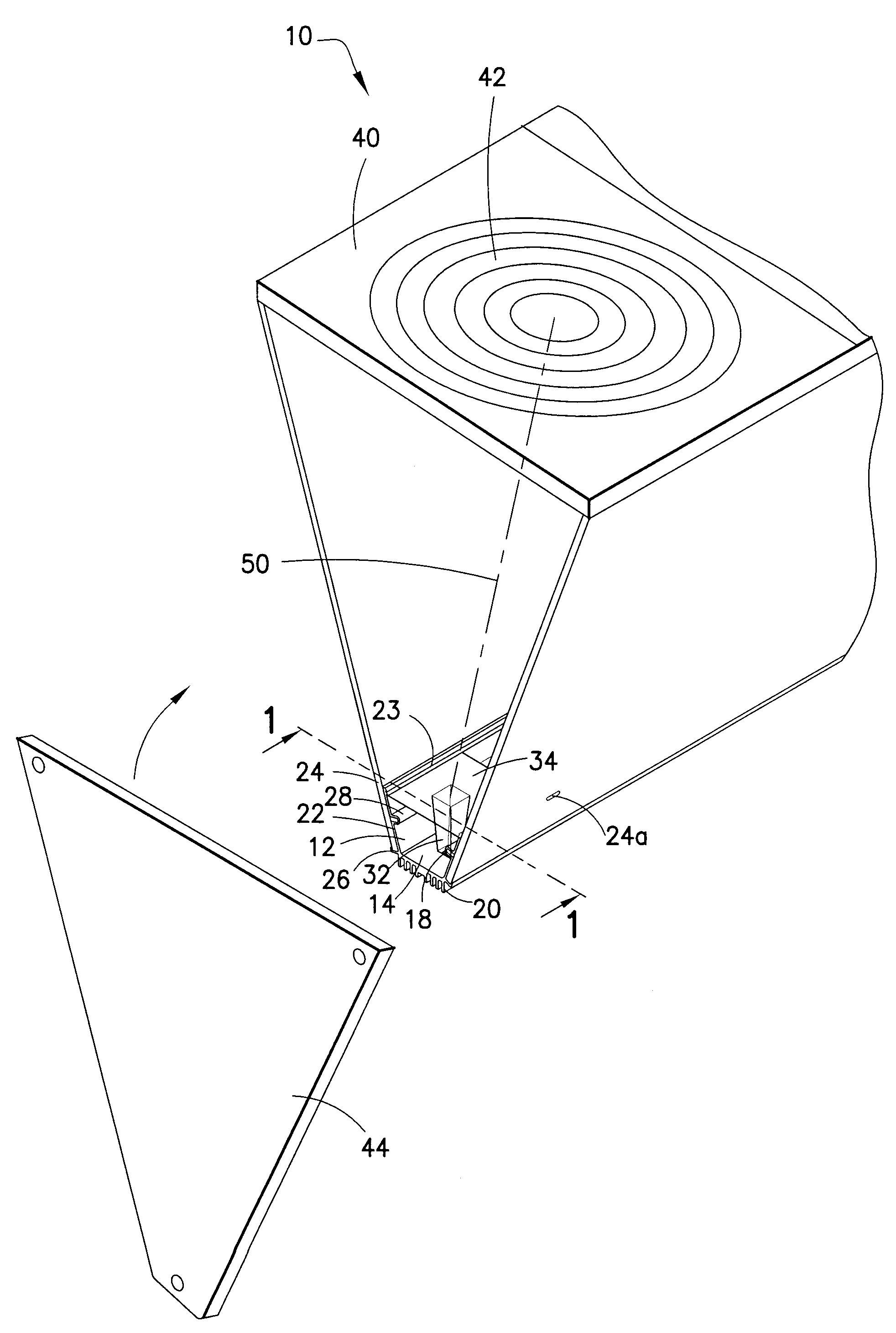
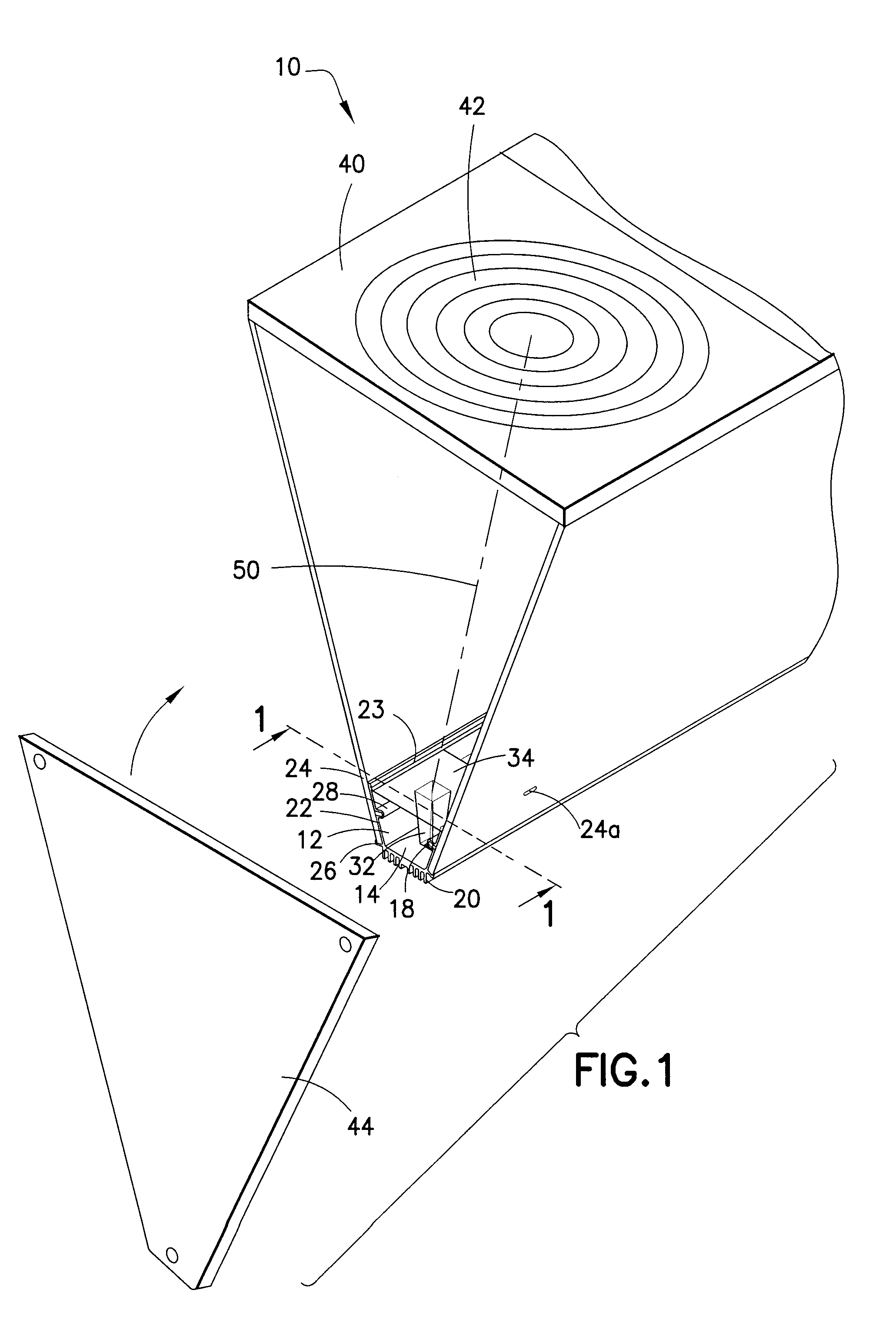
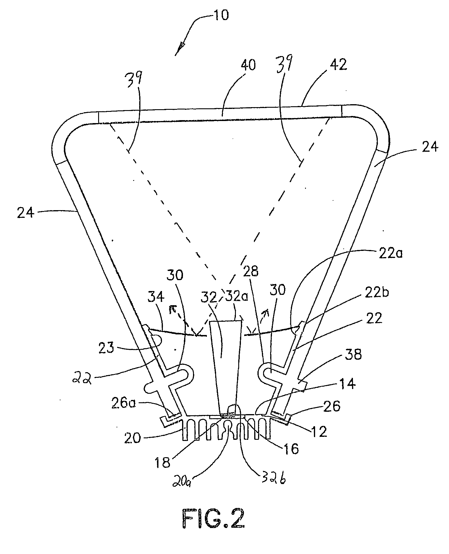
[0033]Referring to FIGS. 1-5, a concentrated solar photovoltaic module 10 of the present invention includes a base member 12 which has a generally planar support surface 14. The support surface 14 contains one or more recesses 16 (FIG. 2) shaped to receive an array of GaAs photocells 18 that are mounted therein, preferably by double-sided thermally conductive tape. The GaA...


PUM


Abstract

A solar photovoltaic module including a base member supporting an array of photocells as well as corresponding concentrating lenses and light guides. At least one opaque light shield defines cutouts corresponding to the light guides. The at least one opaque light shield is positioned above the base member and operates to block light incident thereon from reaching portions of the base member. The at least one light shield can be installed with a convex shape that directs condensation away from the cutouts and preferably functions as part of guide channels that guide condensation toward one or more vented hydrophilic members (e.g., sponges and the like), which are preferably disposed at one or both ends of the module.

Description

CROSS-REFERENCE TO RELATED APPLICATION[0001]This application is a continuation-in-part of U.S. Ser. No. 11 / 928,154, filed Oct. 30, 2007, the contents of which are hereby incorporated herein by reference.BACKGROUND OF THE INVENTION[0002]1. Field of the Invention[0003]This invention relates generally to the field of photovoltaic systems. More particularly, this invention relates to concentrated solar photovoltaic systems and parts thereof.[0004]2. State of the Art[0005]Terrestrial solar photovoltaic systems convert solar insolation into electrical energy using photovoltaic cells. The amount of electrical energy that a photovoltaic cell produces is proportional to the intensity of the insolation it receives and the surface area of the cell. Photovoltaic cells are typically made from either silicon or gallium arsenide. Silicon photocells are less efficient at converting solar insolation to electrical energy, and thus require a larger size and a greater number of cells to provide a requi...

Claims


Application Information

Patent Timeline
Patent Type & Authority Applications(United States)
IPC IPC(8): H01L31/052
CPCH01L31/02021H01L31/048Y02B10/12H01L31/0547H01L31/0475H01L31/0543Y02E10/52Y02B10/10
Inventor LINKE, EDWARD J.
Owner OPEL SOLAR INC
Why Eureka
Try Eureka